MS Composit MS-044 Manuale utente

HEADING-LOCK GYRO MS -044
INSTRUCTIONS MANUAL
Dear Customer,
Thank you for purchasing this genuine MS Composit product.
The fully digital, high rate mini-piezogyro MS-044 is designed for use in electric RC helicopter models of all sizes -starting from the
micro-helis, such as Hornet, up to the large ones.
The MS-044 Piezo Gyro has two operation modes:
1.Standard Mode is normal gyro function, with the gyro gain controlled remotely through an RC equipment channel or by a trim.
2.Heading Lock Mode is designed for keeping the helicopter stable during aerobatic flight, when the demand for keeping the hell
straight is extremely high.
Both modes are switchable during the gyro operation, whilst in flight, as well as the gain of the gyro in the selected mode.
If the RC equipment does not have a free channel for the gyro gain and mode setup, this task can still be done using a trim.
The MS-044 gyro provides a function of an electronic servo travel LIMIT, which eliminates the risk of mechanical servo overload.
The MS-044 gyro provides a Controllable Delay function, which enables fine-tuning of the System depending an the heli weight and
servo speed. This function is not available, when the gyro gain is set manually by a trim.
The gyro provides the function of Authority Mixing -a proportional decrease of gyro sensitivity to the stick control input. The higher the
control input, the smaller the gain -this prevents the gyro to „override" the pilot control inputs.
Gyro sense reversal is achieved simply by turning the gyro upside-down, so check the proper sense before the gyro is installed!
To get the most out of the MS-044, use fast servo for the controlled function! For micro hell Hornet, we recommend use of MS-007
Microservo MS 10, or equivalent with a speed at least 0,09sec/60°.
MS-044 INSTALLATION
To install the MS-044, use the attached double-sided self adhesive tape, which absorbs :malt vibrations. Fix the gyro an a clean surface
for good tape adhesion. The mounting surface should be rigid enough to avoid self generated vibrations during the mode) operation.
Install the gyro in a vertical position, parallel to the axis of model rotation, see picture. It is not recommended to use the servo backside
for the installation, due to high vibration transfer to the gyro.
Place the gyro and it's cables as far as possible from the electrical interference sources -motor, speed controller.
The `gyro must not contact either any moveable mode) parts, nor any other parts of the model, so the vibration transfer to the gyro is
minimised. For the same reason, do not fix the gyro cables at a distance closer than 30 mm from the gyro.
GYRO FUNCTION SETUP
The upper trim, marked GAIN/DELAY serves for the selection of the gyro mode and the gyro gain in the case when the gyro gain cable
is NOT attached to a receiver channel, i.e. When the gyro mode and gain are set locally without using RC equipment.
When the gyro gain cable is attached to !he receiver, the trim sets up the gyro Delay function.
The lower trim, marked LIMIT, sets the electronic limits to the servo travel, preventing the servo and/or the mechanical system from
damage. The bigger the trim setting, the bigger the servo travel. The servo travel is setfor both sides at once.
ATTENTION! For security reasons, the trims are not read by the gyro in real time, but only at the gyro calibration time after
gyro power on. Therefore, when changing the trim setting, it is mandatory to „reboot" the gyro by switching the power off and
on.
The LED control light status:
When the LED light is an -the gyro performs inicialization procedures, read-out of the trims and the sensors. In this phase, do not
move the model, do not touch the transmitter sticks, otherwise the gyro will not function properly.
When the LED light is off -the inicialization procedure has ended, the gyro is ready for operation, and there is no control input signal
an the channel, controlled by the gyro.
When the LED light blinks -the gyro is in operational mode, and there was a control input detected an the channel, controlled by the
gyro. This possibility of checking the presence (or absence) of the control signal is very useful, when finding out reasons of improper
gyro function -the blinking LED will immediately tell you, that for example some unwanted mix (as REVO mix), was left activated in
the transmitter.

BASIC SETUP
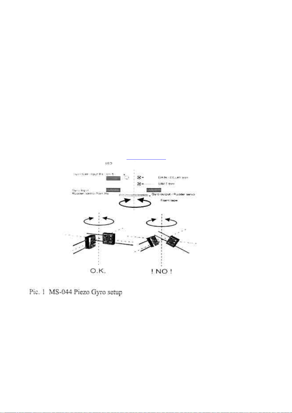
After the MS-044 installation it is needed to setup the gyro corresponding to the application.
Servo Limit Setup
Firstly, a setup of the servo travel Limit must be set up corresponding to the mechanical possibilities of the tail control system. Start with
setting the LIMIT trim to approximately 75% then reset the gyro (by power off and on). Check if the maximum mechanical travel is not
smaller than the electronic one (the rods will bend, or the servo will buzz). If yes, decrease the LIMIT trim, reset the gyro and check
again. This is an repetitive process, which is, of course, influenced among others by the servo horn length.
For MS 10 servos, the proper distance between the control pushrod link and the horn rotation axis is 8-10 mm. For other servos, adjust
the horn in a way the LIMIT trim value is in range of 75°%o -100%.
Attention! When setting up the gyro LIMIT function, the electronic travel limit in the transmitter must be set to 100% (i.e. No
limit of the servo travel), or, if this is not possible, the maximum mechanically available value! After the gyro setup, it is
recommended to adjust the electronic servo travel in the transmitter in such a way, so that the servo travel limit an the transmitter is the
same as an the gyro. This eliminates a „dead zone", which occurs if the gyro limit is set to a lower value, than the maximum travel setting
an the transmitter.
Gyro Mode Selection and Gain Setup
The gyro mode selection and gain setup is performed either by a GAIN%DELAY trim, or by a transmitter channel.
In Gases when the trim is used for the Mode and Gain setup:
If the GAIN/DELAY trim is set to 50% (middle of the entire travel), the gain is minimal.
If the trim knob is turned counter-clockwise (the value is decreased from 50 to 0%), the gyro is set to the Standard Mode, and the gyro
gain is indirectly proportional to the trim value (the lower the value, the higher the gain) in the Standard Mode.
If the trim knob is turned clockwise (the value is increased from 50 to 100%), the gyro will operate in Heading-Hold Mode, and thee
gain is directly proportional to the trim
Value -the higher setting. the higher gain.
Don't forget to reboot the gyro after each trim setting change, otherwise the new setting will not he accepted by the gyro.
In cases when a radio channel is used for the Mode and Gain setup:
If a free radio channel is used to control the gyro mode and gain, the mode and gain can he changed anytime during the gyro
Operation. Normally Channel No. 5 is used (or the gyro control. This channel is connected to a slider (or switch), and the gyro control
itself is very similar to a control by the trim.
If the value of the channel is below 50%, the gyro is in Standard Mode, and the gain is indirectly proportional to the channel setting (the
lower the setting, the higher the gain.
1fthe value of the channel is above 50%, the gyro is in Heading-Lock mode, and the higher the channel value, the higher the gyro gain.
When using the slider, we recommend to set the maximum values of the channel so they correspond to the maximum usable gyro gain.
The maximum gain is recognized by a very slight wagging of the tail of the heli in flight. More convenient is to control the gyro mode
and gain by a switch. In such a case we strongly recommend to set the channel values so that there is a small reserve to the maximum
possible (on the particular model) gain, because there is no way to quickly reduce the gain when the switch is activated. 1 the Standard
Mode is used. normally a REVO-mix is set up in the transmitter. For the Heading-Lock Mode, the REVO-mix MUST BE DISABLED!
The active REVO-mix will cause an error in the tail neutral position during the flight. If you whish to use the gyro in both modes, we
recommend to use the Standard Mode for hover, where the REVO-mix is not a crucial function, and Heading-Lock Mode for aerobatics.
If your transmitter al lows, you can combine die gyro mode setup, REVO-mix activation with the idle-up or other throttle
controls.
Delay Setup
1his function is active only if the gyro Mode and Gain is set from a transmitter -the function activates when the gyro gain cable is fitted
to the receiver. The right setup of the gyro Delay function will depend an the mode) type, and pilot's preferences. Typically, the smaller
the model, and the slower the tad servo, the lower the Delay trim value. For Hornet hell, the initial setup is 0.
MS-044 OPERATION
Gyro MS-044 is designed for use also in very small helicopters, where the ratio between the tail rotor weight and the tail servo speed is
very inconvenient for precise tail control.
Hic lighter the tail, the Duster is the tail position change, and the Taster must be the servo and the gyro, if the System is to be stable
even in complicated aerobatic situations, or fast backward flight.
Because of the overall flight dynamics of very small models, in the Heading-Lock mode it is normal when the tail slightly oscillates in
hower in complete still (indoor). This is caused by a fact the model can not react an a very small gyro corrections. This effect disappears if
the System is loaded by any control command, change of the main rotor torque or by movement in any direction. ATTENTION -similar
effect as described above can he caused by vibrations transferred to the gyro. Such excessive vibrations are usually caused by incorrectly
mounted (too tight) main rotor blades, or non symmetrically mounted tail rotor blades. If the tail oscillation is too high and if it does not
disappear when the gyro operates in Standard Mode, check the hell setup!
In a dynamic flight the MS-044 gyro provides excellent stabilization.

The effect discussed can be eliminated by increasing the tail weight, for example by moving the tail servo backwards (to the tail fin, the
model balancing remains the Same if the accus are moved forward), or by using Standard Mode for hover flight. The gyro gain can be
set in quite broad range, when model is still stabilized. and does not wag the tail. The heavier the model, the higher gyro gain can be
used. We recommend to trim the neutral tail position in Normal Mode. This will eliminate possible mechanical deviation of the tail
neutral position. Such a deviation will load the gyro with all-time correction of the neutral, leading subsequentially to unequal steering
effect for left and right deviations.
Also, bear in mind that if substantial trimming took place, the steering deviations will be different for left and right side. This is because
of the Authority mixing system, which decreases the gyro sensitivity taking into account the original neutral position, but this position
was substantially changed by the trimming. Resolve the Situation by reboot of the gyro (power off and on).
OPERATIONAL CONDITIONS
The operating voltage is 4 -6,5 V. If the upper allowable voltage is exceeded, the gyro will be irreversibly damaged.
The Position sensor inside of the gyro is very sensitive to mechanical shock and vibrations. Avoid hard hits, as this will lead to
terminal gyro damage. The temperature range: -10 -+ 50°C, avoid rapid temperature changes. We wish you many happy flights
with our product!
MS Composit s.r.o.
Tursko 37
Czech Republic
www.mscomposit.com
Indice
Altri manuali MS Composit Giocattolo

MS Composit
MS Composit Ultimate MS-35000 Manuale utente

MS Composit
MS Composit Hornet Istruzioni utente

MS Composit
MS Composit SWIFT MAXI Manuale utente

MS Composit
MS Composit BladeDancer MS-14 000 Manuale utente

MS Composit
MS Composit ULTIMATE 600 Manuale utente

MS Composit
MS Composit MS Hornet II MS-700 Manuale utente

MS Composit
MS Composit SWIFT Manuale utente


