Table of Contents
1 Safety
1.1 General conditions 7
1.2 Personnel and organizational requirements 8
1.3 Transport 9
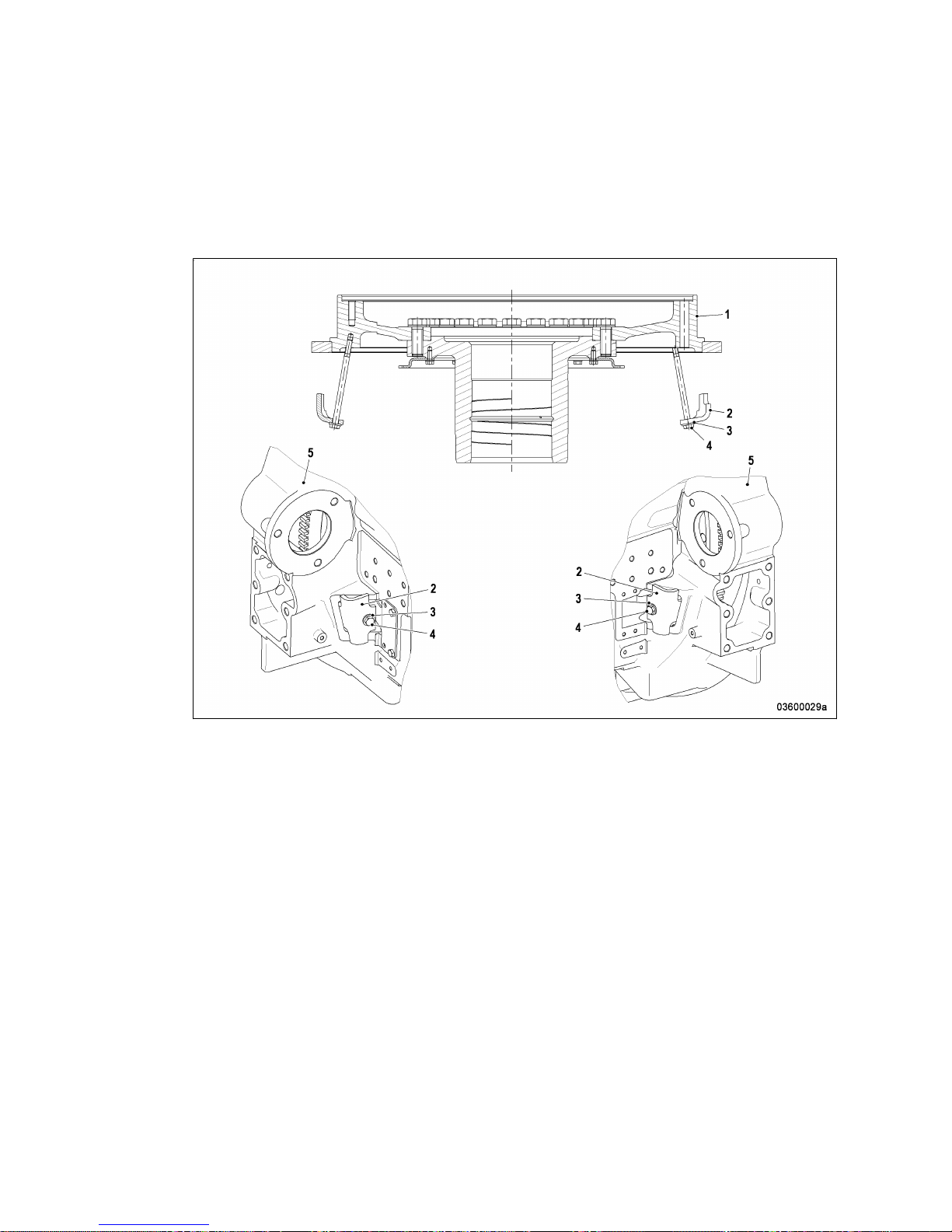
1.4 Crankshaft transport locking device – For
transport with flanged-on generator 10
1.5 Safety regulations for startup and operation 12
1.6 Explosion hazard when removing
inspection port cover on engine 13
1.7 Safety precautions when working on the
engine 14
1.8 Fluids and lubricants, fire prevention and
environmental protection 16
1.9 Conventions for safety instructions in the
text 18
2 General Information
2.1 Engine side and cylinder designations 19
2.2 Engine layout 20
2.3 Sensors, actuators and injectors –
Overview 23
3 Technical Data
3.1 20V 4000 C22 engine data 27
3.2 Firing order 31
3.3 Main engine dimensions 32
4 Operation
4.1 Putting the engine into operation after
extended out-of-service periods (>3
months) 33
4.2 Putting the engine into operation after
scheduled out-of-service-period 34
4.3 Engine – Start in manual mode 35
4.4 Operational checks 36
4.5 Engine – Shutdown in manual mode 37
4.6 After stopping the engine 38
4.7 Plant – Cleaning 39
5 Maintenance
5.1 Maintenance task reference table [QL1] 40
6 Troubleshooting
6.1 Troubleshooting 41
6.2 ECU 4 alarms 44
7 Task Description
7.1 Engine 56
7.1.1 Engine – Barring manually 56
7.1.2 Engine – Barring with starting system 58
7.2 Cylinder Liner 59
7.2.1 Cylinder liner – Endoscopic examination 59
7.2.2 Instructions and comments on endoscopic
and visual examination of cylinder liners 61
7.3 Crankcase Breather 63
7.3.1 Crankcase breather – Oil separator
replacement, diaphragm check and
replacement 63
7.3.2 Crankcase breather – Cleaning 65
7.3.3 Crankcase breather – Filter element
replacement 66
7.4 Running Gear 68
7.4.1 Grounding device – Removal and installation 68
7.4.2 Grounding device – Replacement 69
7.5 Valve Drive 70
7.5.1 Valve gear – Lubrication 70
7.5.2 Valve clearance – Check and adjustment 71
7.5.3 Cylinder head cover – Removal and
installation 76
7.6 Injection Pump / HP Pump 77
7.6.1 HP fuel pump – Relief bore check 77
7.7 Injection Valve / Injector 78
7.7.1 Injector – Replacement 78
7.7.2 Injector – Removal and installation 79
7.8 Fuel System 85
7.8.1 Fuel system – Venting 85
7.9 Fuel Filter 86
7.9.1 Fuel filter – Replacement 86
7.9.2 Edge-type fuel filter – Draining 87
7.9.3 Fuel prefilter – Draining 88
7.10 Charge-Air Cooling 89
7.10.1 Intercooler – Check drain for coolant leakage
and obstruction 89
7.11 Air Filter 90
7.11.1 Air filter element and dust bowl – Cleaning 90
7.11.2 Air filter – Replacement 92
M015675/05E 2011-10 | Table of Contents | 5
DCL-ID: 0000014250 - 001