Multitech MR4800E Manuale utente

MultiModemManager
MR4800E Rack Controller
Owner’s Manual

MR4800E Rack Controller
Owner’s Manual
P/N 82042403, Revision D
This publication may not be reproduced, in whole or in part without prior expressed written
permission from Multi-Tech Systems reserved.
Copyright © 1996, by Multi-Tech Systems, Inc.
Multi-Tech Systems, Inc. makes no representation or warranties with respect to the contents hereof
and specifically disclaims any implied warranties of merchantability or fitness for any particular
purpose. Furthermore, Multi-Tech Systems, Inc. reserves the right to revise this publication and to
make changes from time to time in the content hereof without obligation of Multi-Tech Systems, Inc.
to notify any person or organization of such revisions or changes.
Revision Description
BManual revised to include World Wide Web Browser
(09/30/96) interface information.
CManual revised to include new commands and technical
(12/16/96) and editorial information.
DManual revised to include new commands and technical
(9/15/97) and editorial information.
Trademarks
Multi-Tech, MultiModem, MultiModemII, MultiModemManager and the Multi-Tech logo are trademarks
of Multi-Tech Systems, Inc.
Multi-Tech Systems, Inc.
2205 Woodale Drive
Mounds View, Minnesota 55112
(612) 785-3500 or (800) 328-9717
U.S. Fax (612) 785-9874
Technical Support (800) 972-2439
BBS (612) 785-3702 or (800) 392-2432
Fax Back (612) 717-5888
InternetAddress: http://www.multitech.com

Contents
Chapter 1 - Introduction & Description
1.1 Introduction ..........................................................................................................................................6
1.2 Product Description .............................................................................................................................6
1.3 Features...............................................................................................................................................6
1.4 Specifications.......................................................................................................................................7
Chapter 2 - Hardware Installation & Quick Starts
2.1 Introduction ........................................................................................................................................10
2.2 Battery Warning .................................................................................................................................10
2.3 Hardware Installation Procedure........................................................................................................11
2.4 Ethernet Cabling ................................................................................................................................11
2.5 Serial Cabling ....................................................................................................................................11
2.6 Quick Starts .......................................................................................................................................12
2.6.1 MR4800E Quick Start.........................................................................................................12
2.6.2 Supervisor Console Quick Start .........................................................................................12
2.7 Supervisor Console Configuration .....................................................................................................13
Chapter 3 - Hardware Operation
3.1 Introduction ........................................................................................................................................16
3.2 Security..............................................................................................................................................16
3.3 File System ........................................................................................................................................16
3.3.1 Event Files..........................................................................................................................16
3.4 SNMP Interface .................................................................................................................................17
3.5 Command Line Interface....................................................................................................................17
3.6 Telnet Interface ..................................................................................................................................18
3.7 Web Browser Interface ......................................................................................................................18
3.7.1 Logging In...........................................................................................................................18
3.7.2 Getting Modem Information ................................................................................................18
3.7.3 Controlling Modems............................................................................................................18
3.7.4 Web Interface Limitations ...................................................................................................18
3.8 FTP Interface .....................................................................................................................................19
3.9 PPP Interface.....................................................................................................................................19
Chapter 4 - Commands
4.1 Parameter Descriptions .....................................................................................................................22
4.2 Commands Listed by Function ..........................................................................................................23
4.3 Commands Listed by Security Level .................................................................................................26
4.4 Command Reference.........................................................................................................................28
4.5 Error Messages .................................................................................................................................52
Chapter 5 - Troubleshooting
5.1 Introduction ........................................................................................................................................56
5.2 LED Indicators ...................................................................................................................................56
5.3 Front Panel Indicators........................................................................................................................56
5.4 Ethernet Status LEDs ........................................................................................................................57
5.5 MR4800E Diagnostic Tests................................................................................................................57
iii

iv
Chapter 6 - Service, Warranty, & Tech Support
6.1 Service...............................................................................................................................................60
6.2 Limited Warranty................................................................................................................................60
6.3 The Multi-Tech BBS ...........................................................................................................................61
6.4 On-Line Upgrade via Flash PEROM and FLASHPRO Software .......................................................62
Index

MultiModemManager
Chapter 1 - Introduction & Description
MR4800E Owner’s Manual
6
1.1 Introduction
This manual is intended to provide the information needed for field installation of a Multi-Tech
MR4800E Rack Controller Module (henceforth, MR4800E) into a previously-installed and operational
CC4800 MultiModemManager rack. The CC4800 is shipped standard without an MR4800E; this
manual documents the installation of an optional MR4800E.
1.2 Product Description
The MR4800E contains the processor and memory for intelligent SNMP management of the modems
in the rack. The front panel contains an RJ45 connection for Ethernet UTP attachment to a TCP/IP
Ethernet network and a 9-pin serial connection for PPP attachment to a remote TCP/IP network. The
front panel provides 16 two-color LEDs for MR4800E card status and 4 Ethernet status LEDs.
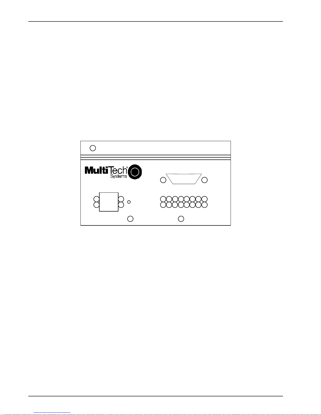
The MR4800E Rack Controller Module front panel is shown below.
MultiModemManager
MR4800E Controller
ETHERNET
Serial Port
Reset
Button
Figure 1-1. MR4800E Rack Controller Module front panel
1.3 Features
The MR4800E is an optional part of the MultiModemManager system, Multi-Tech System’s high-
density intelligent modem/rack facility with network management capability. When you have installed
the MultiModemManager hardware and software, you will gain centralized modem rack
management to control modems, continuously monitor connections, log the data, and report fault
events.

Chapter 1 - Introduction & Description
7
1.4 Specifications
The MR4800E is designed to meet the following specifications:
• contains one Motorola MC68360 25 MHz microprocessor
• provides 8 MB of RAM for volatile storage
• provides 2 MB of flash RAM: 1 MB for program space and 1 MB for nonvolatile file system
space
• provides Ethernet 10Base-T connector which is an RJ-45 for LAN connection to a TCP/IP
Ethernet network
• provides EIA RS-232C connector for PPP connection to a TCP/IP Ethernet network
• provides one RS-232C configuration port out of the back of the rack
• 16 two-color LEDs for quick view of modem card status
• 4 Ethernet status LEDs
• Recessed reset button
• Dimensions: 1.75 x 4.2 x 15 inches (HxWxD)
4.2 x 11.5 x 37.4 cm (HxWxD)
• Weight:1.0 Lbs. (0.45 Kg.)
• OperatingTemperature: 00 to 500 (320to 1200F)
• Power Requirements: 60 Hz, 600mA@5V
• Limited Warranty: Five years

MR4800E Owner’s Manual
8

MultiModemManager
Chapter 2 - Hardware Installation & Quick Starts
MR4800E Owner’s Manual
10
2.1 Introduction
This chapter provides the information needed to install your MR4800E Rack Controller into a Model
CC4800 MultiModemManager Rack. This equipment should only be installed by properly qualified
service personnel.
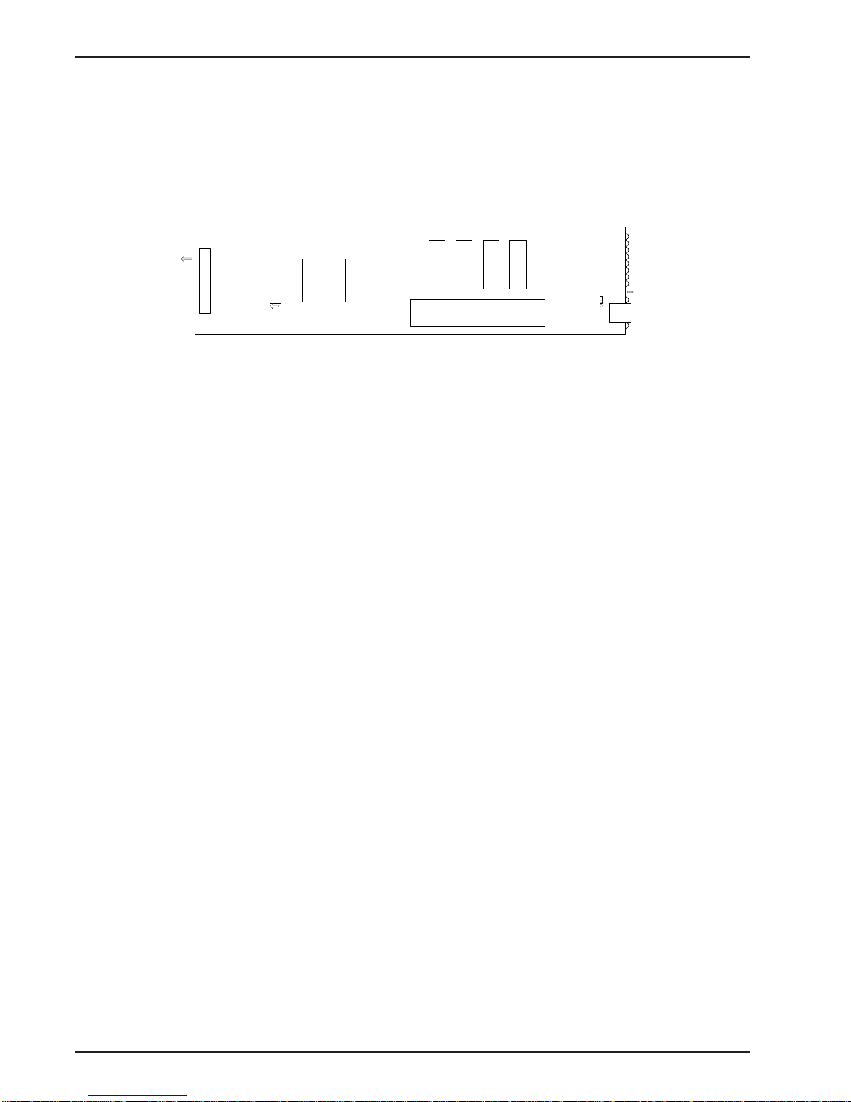
The MR4800E is illustrated below ( shown with the factory defualt configuration settings),
Connector
Ribbon connector
CPU
Flash ROMs
Memory SIMMs
U4 U5 U7 U6
Test Jumper
Ethernet
connector
LEDs
To
back
panel
config/
debug
port
Reset
Button
Figure 2-2. MR4800E Rack Controller Card
2.2 Battery Warning CAUTION
Danger of explosion if battery is incorrectly replaced. Replace only with the same or equivalent type
recommended by the manufacturer. Dispose of used batteries according to the manufacturer’s
instructions.
The MR4800E Controller circuit board includes a battery that maintains the MR4800E’s setup
information when the MultiModemManager is turned off or disconnected from power. The battery can
maintain the setup information for approximately 10 years with no external power, and longer when
the MR4800E is turned on and operating normally. This battery is soldered onto the circuit board and
cannot be replaced by the user.
If, for some reason, the MR4800E’s battery should fail, please contact Multi-Tech Technical Support
at (800) 972-2439 for replacement instructions.
Indice
Altri manuali Multitech Controllori


