Neuro Logic Systems NLS 1U Server Console RFT-17 Manuale utente
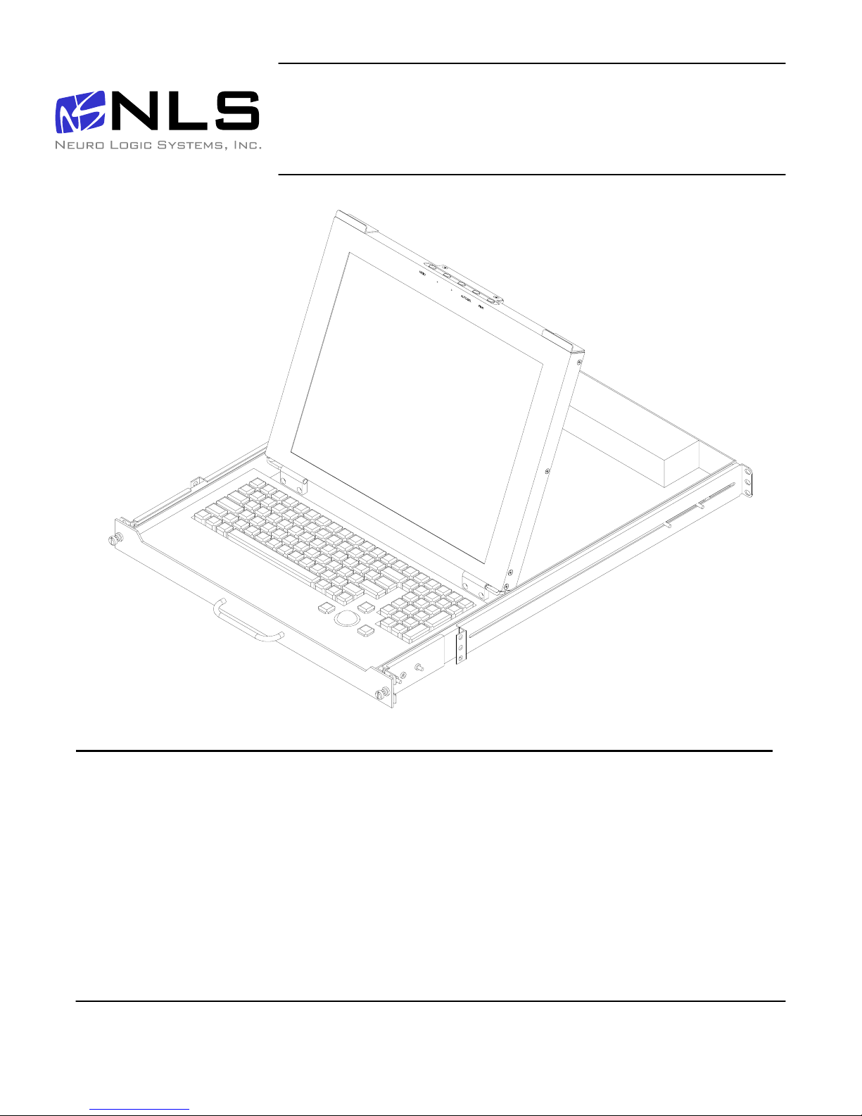
17 inch LCD/Keyboard Rack Kit
Installation guide for the RFT-17 Line
into a 4-post 19-inch EIA cabinet
Page 1 of 14
Table of Contents
Hardware Installation… …………………………………………………………………… 2
Connecting your LCD/Keyboard………………………………………………………… 5
Operating your LCD/Keyboard..…………………………………………………………. 6
Navigating the Menu.………………………………………………………………………. 8
On-Screen Display (OSD) Menus………………………………………………………… 9
Trouble Shooting Bad Image Quality…………………………………………………… 10
Specifications………………………………………………………………………………. 12
Warranty……………………………………………………………………………………… 13
Neuro Logic Systems, Inc. 02/01/05

17 inch LCD/Keyboard Rack Kit Installation Guide
Page 2 of 14
17 inch LCD/Keyboard Rack Kit Installation Guide
Hardware Installation
Step Detail
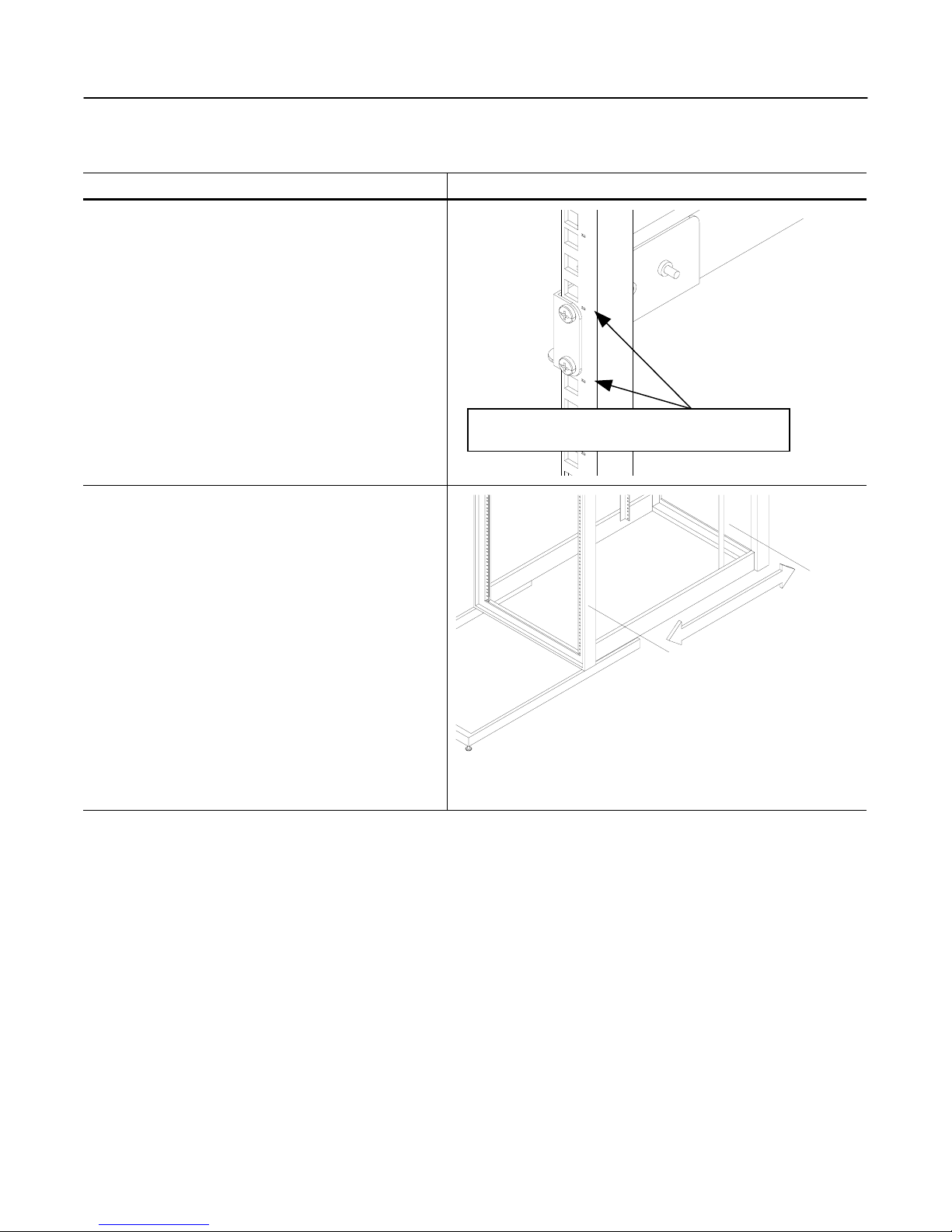
1. Determine the vertical location for the LCD/keyboard
in the rack. Mark the location with tape or a pencil.
This product requires one rack unit (1 ¾”) of vertical
space. Mount the LCD/keyboard at a convenient
height for an average user. (Approx 44” from floor)
2. Measure the distance from the front rack mounting
rail to the rear rack mounting rail. (This distance will
be needed during installation of the Rear slide
mounting brackets in step 4)
Distance= _____________
Ensure the bottom of the kit is properly positioned in a
rack unit
Page 3 of 14
17 inch LCD/Keyboard Rack Kit Installation Guide
Step Detail
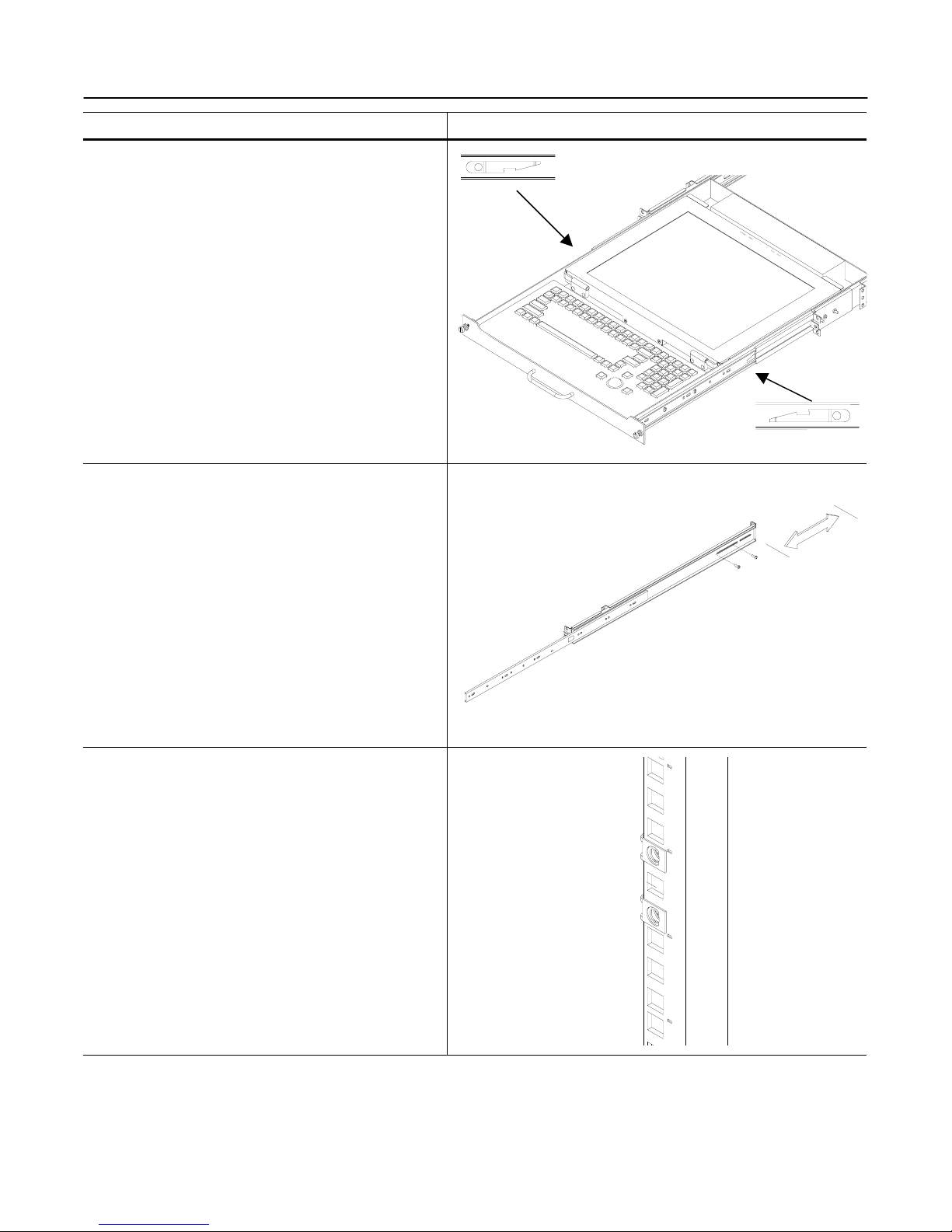
3. Remove the slides from the tray assembly. The
slides come shipped attached to the tray assembly,
the outer slide members must be removed to be
properly installed into the rack. To remove the outer
slide members, fully extend both slides to the open
position. Once extended unlock the outer slide
members by lifting up on the left side latch and
pressing down on the right slide latch. The outer
slide member can now be removed from the tray
assembly. The inner slides are left attached to the
tray assembly.
4. Adjust the rear slide mounting brackets to the proper
depth. The rear slide mounting brackets are pre-
assembled, but may need to be adjusted to the
proper distance measured in step 2. There is
multiple screw holes in the rear slide mounting
brackets and slide rails. You can use any of these
holes. Do not tighten screws until after you install the
slides in the rack, as you may need to make small
adjustments.
5. Insert nut clips into the rack mounting rails as
required. If your rack has square or round untapped
holes, you will need to use 10-32 nut clips.
Lift Up
Push Down
Page 4 of 14
17 inch LCD/Keyboard Rack Kit Installation Guide
Step Detail
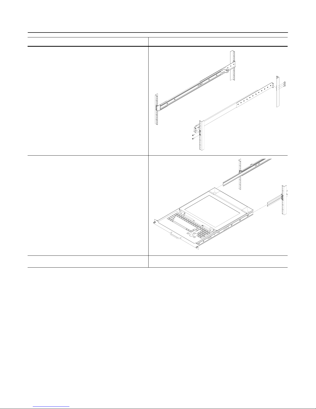
6. Attach the left slide rail assembly to the rack
mounting rail by using (6) #10-32 x ½” screws for the
front and rear slide mounting brackets. Repeat for
the right slide rail assembly.
7. Tighten the screws that attach the rear slide mount
bracket to the outer slide member. (From step 4)
(4X)
8. Extend the slides from the rack.
9. Install the LCD/keyboard assembly into the rack. Lift
the tray assembly and approach the rack with the
rear of the tray facing the rack enclosure. Align the
tray assembly with the slide rails in the rack.
Carefully assemble the two slide members together.
Push the tray assembly in until the slides latch
together. Release the lock mechanisms as shown in
step 3 in order to slide the tray assembly completely
closed.
Page 5 of 14
17 inch LCD/Keyboard Rack Kit Installation Guide
Connecting your LCD/Keyboard
Step Detail
! Note: Before connecting the LCD monitor/keyboard to a
KVM or Sun System, all systems should be turned off.
1. The keyboard and trackball’s design allows its use with
most Sun systems. The LCD-17-8P com es with an 8-
pin Din keyboard connector, while the LCD-17-USB
comes with a USB style connector.
2. The monitor uses a standard HD-15 male video
connector. If your Sun system uses a DB13W3
connection, you can use a Sun adapter to interface
between the LCD connector and the Sun system. (PN:
X3872A)
3. Connect the monitor to a power source. The LCD
Monitor’s power supply is auto ranging, and will operate
on AC voltages ranging from 90-264 and 50-60 Hz. The
monitor uses an IEC 320-C14 connector. An adapter will
be required to interface with other connector types.
4. Secure the cables to ensure they will not bind when
operating the LCD/keyboard slide mechanism. Cycle the
tray in and out of the cabinet to ensure there is enough
of a service loop in the cables.
Page 6 of 14
17 inch LCD/Keyboard Rack Kit Installation Guide
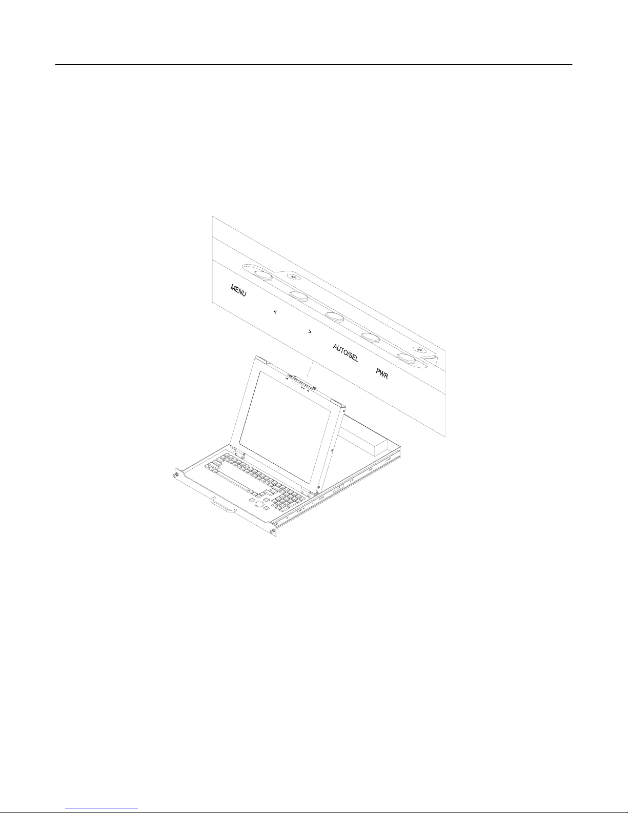
Operating your LCD/Keyboard
NOTE: It is important to ensure that the monitor is connected and powered on prior to powering up the connected
Sun system. By powering up the Sun System last it will allow the frame buffer within the Sun system to
communicate with the LCD monitor and self configure to the correct settings.
After the unit has been installed and all cables connected, power on the LCD monitor by lifting the head unit.
(There is a power button at the rear of the LCD which is actuated by lifting the head of the LCD monitor.) The LED
situated on the top of the LCD panel will alert you to its status. It will illuminate green when everything is working
properly. If the LED is orange, the monitor is powered up but not receiving a valid video signal.
NOTE: If the monitor does not power up automatically when raised, the power button at the rear of the monitor
may need to be cycled. There is also a Power button on the top of the LCD which may also need to be cycled.
Once the LCD monitor is powered on, power on the connected Sun system and log in (or otherwise ensure that a
full screen image is displayed). Now press the monitor AUTO/SEL button. This will Auto-adjust the display to
optimum performance.
NOTE: It is important to ensure that a full screen image is being displayed at the time the monitor is in the Auto-
Adjust function. The display may be miss-positioned if an image with a black border (such as a CDE login Screen)
or partial screen is used.
NOTE: The display resolution should self configure to 1280x1024 resolution at 60Hz. With some older Creator
and Creator3D frame buffers, the monitor will self configure to 1152x900 resolution at 66Hz. This is normal since
these old frame buffers do no support 1280x1024x60Hz resolution. To check the current resolution of the monitor,
Page 7 of 14
(On some models the menu panel may be located on the back of the LCD)

17 inch LCD/Keyboard Rack Kit Installation Guide
press the Menu button at the rear of the LCD panel twice, which will select the Display Mode menu. Note that
deviations of a fraction of a hertz in the displayed refresh rate are not significant.
NOTE: If the monitor self configures to any other resolution, it is likely that the frame buffer has been explicitly
configured to display that particular resolution. If running Solaris 8 or above, use the “fbconfig –defaults”
command to reset the resolution to the default, and then reboot the system. With earlier versions of Solaris, use
the appropriate command for your particular frame buffer (E.g. “ffbconfig – defaults” for the Creator[3D] frame
buffer).
Page 8 of 14
17 inch LCD/Keyboard Rack Kit Installation Guide
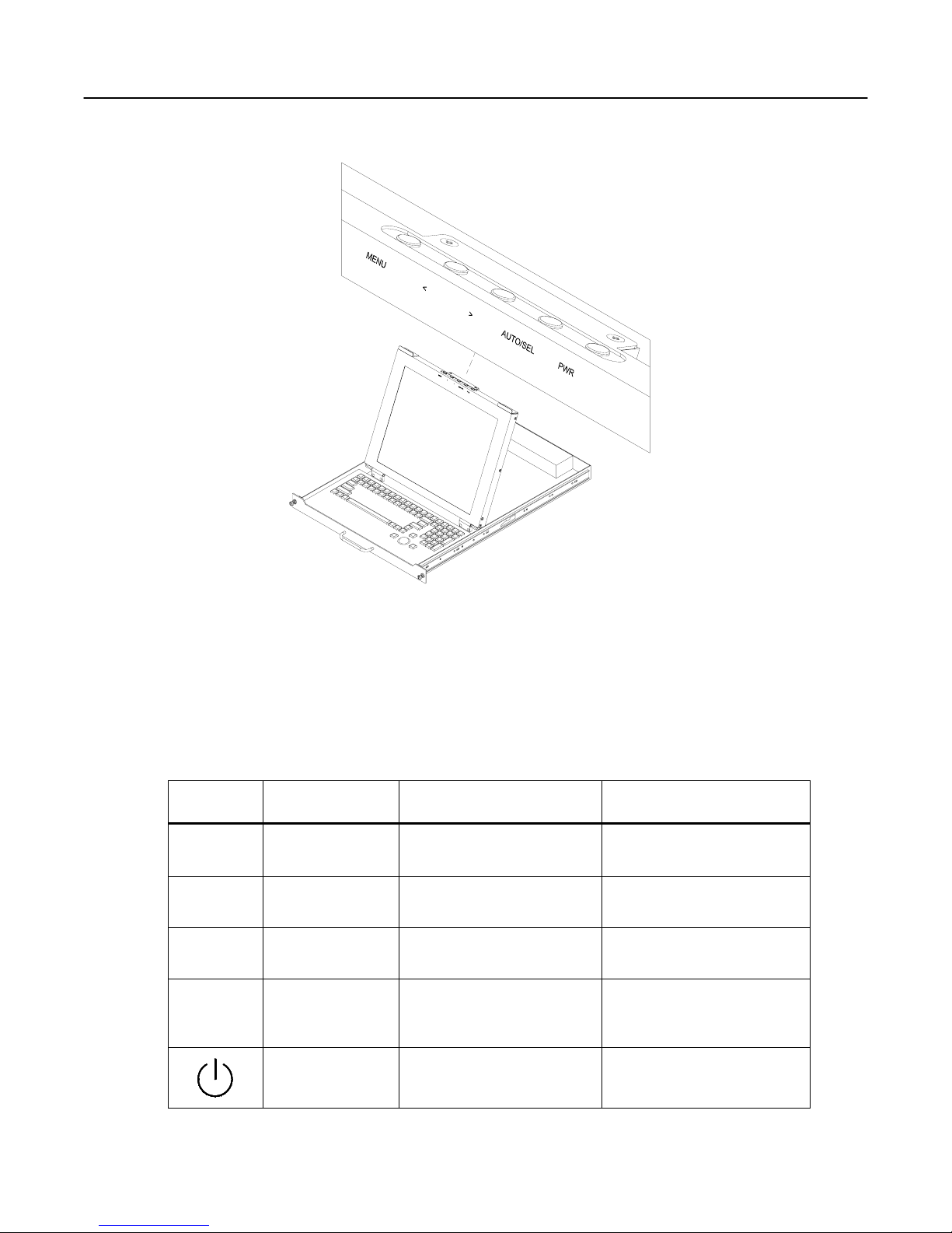
Navigating the Menu
The LCD monitor will auto-adjust at start-up. Although not required, you can make numerous adjustments to your
monitor using the on-screen menu. To access the OSD (On-Screen Display) menu Press the MENU button
located at the top of the LCD monitor.
The table below describes various function controls of the LCD Monitor. The control buttons can be accessed
from the top of the LCD monitor once it has been raised in to the operating position. The OSD menu will
disappear after a pre-set time of no use.
Label Control Function when not
displaying menu Function when displaying
menu
MENU Menu button Displays the On-Screen
Display (OSD) Selects the next page of the
menu
< Brightness/minus Decrease display brightness Decreases or changes value
of the adjustment item
> Brightness/plus Increase display brightness Increases or changes value of
the adjustment item
AUTO/SEL Auto/Select Activates the Auto Adjust
function to obtain an optimum
image
Selects a menu item
Power switch Turn power on and off
manually Turn power on and off
manually
Page 9 of 14
(on some models the menu panel may be located on the back of the LCD)
17 inch LCD/Keyboard Rack Kit Installation Guide
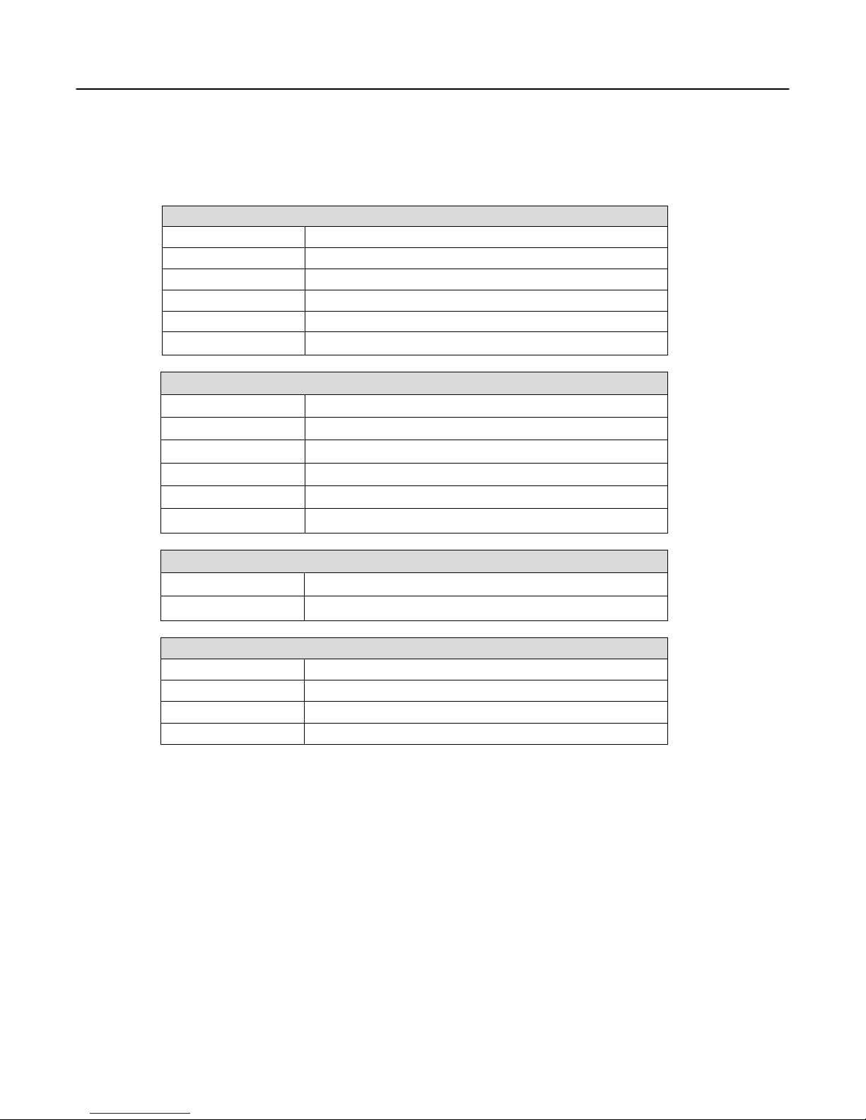
On-Screen Display (OSD) Menus
The menu pages can be displayed by pressing the Menu button. Not all menu functions can be adjusted. (Menu
items or layout may change without notice)
Menu Page 1
Auto-Adjustment This function is used to obtain an optimum image
Contrast Adjusts the contrast of the display
Horizontal Position * Changes the horizontal position of the image
Vertical Position * Changes the vertical position of the image
Frequency * Changes the display data frequency
Tracking * Synchronizes the signal timing
Menu Page 2
Display Mode Displays the current resolution and frequency
OSD Off Time Adjusts the time that the OSD takes to disappear
Language Selects the OSD language
Text-Graphic Mode Not available for change
Sharpness Not available for change
Reset Resets the monitor to factory default settings
Menu Page 3
Volume Sound not implemented
Mute Sound not implemented
Menu Page 4
Color Setting Adjusts the color temperature
Color Adjust - Red Adjusts the amount of red in the image
Color Adjust - Grn Adjusts the amount of green in the image
Color Adjust - Blue Adjusts the amount of blue in the image
* Auto-Adjustment will reset all parameters to the factory default.
Page 10 of 14
Indice
Altri manuali Neuro Logic Systems Cassetto LCD

Manuali Cassetto LCD popolari di altre marche

Acnodes
Acnodes KD 8228 Manuale utente

Ameriwood
Ameriwood 9524328PCOM Manuale utente

Kesseböhmer
Kesseböhmer TANDEM solo Manuale utente

Crystal Image Technologies
Crystal Image Technologies RMD-151-A Series Manuale utente

APW Wyott
APW Wyott Ease Extreme HDX-1-120 Manuale utente

NTI
NTI RACKMUX-V17-N Manuale utente


GRASS
GRASS DWD XP Manuale utente

StarTech.com
StarTech.com DuraView RACKCONS1701 Manuale utente

Fisher & Paykel
Fisher & Paykel IZONA CoolDrawer RB36S Manuale utente

Synergy Global Technology
Synergy Global Technology LCD1U17-44 Manuale utente

Fujitsu
Fujitsu RC25 Manuale utente

Acnodes
Acnodes RK 1000B Manuale utente