NEUTRIK NPPA-TT-IDC Manuale utente
NEUTRIK AG NEUTRIK Zürich AG NEUTRIK (UK) Ltd. NEUTRIK USA INC. NEUTRIK Tokyo Ltd. NEUTRIK France NEUTRIK Vertriebs GmbH
Liechtenstein Switzerland Great Britain USA Japan France Germany/Netherlands/Austria
Tel.: +423/237 24 24 Tel.: +41 44/736 5010 Tel.: +44 1983/811 441 Tel.: +1 732/901 9488 Tel.: +81 3/3663 4733 Tel.: +33 1/4131 6750 Tel.: +49 8131/28 08 90
Fax: +423/232 53 93 Fax: +41 44/736 5011 Fax: +44 1983/811 439 Fax: +1 732/901 9608 Fax: +81 3/3663 4796 Fax: +33 1/4131 0511 Fax: +49 8131/28 08-30
www.neutrik.com
Draft. Nr.: BDA98-1/ 3102M0881
Update: 03.08.2009
Data subject to change without prior notice. ©2007 NEUTRIK . ALL RIGHTS RESERVED.
INSTRUCTION MANUAL
NPPA-TT-IDC
PATCH PANEL “Easy Patch” | 96 Bantam (TT) Jacks,
IDC Termination

Page 2 of 11
NPPA-TT-IDC Instruction Manual
Index
1. Electrical configuration ............................................................................................3
2. Grounding variations................................................................................................4
3. Wiring.........................................................................................................................5
4. Cable retention..........................................................................................................7
5. Channel identification...............................................................................................7
6. Replacement..............................................................................................................9
7. Technical data .........................................................................................................11
8. Content of supply....................................................................................................11
Dimensional Drawings “Easy Patch” NPPA-TT-IDC
Front panel Cable retention bar Top cover

Page 3 of 11
NPPA-TT-IDC Instruction Manual
1. Electrical configuration
The Neutrik ”Easy Patch” Patch Panel is fitted with high quality, long life NJ3TTA gold plated
double contact jacks (2 x 48). This Patch Panel is an innovative and compact patching system
(just 1 U high) for 19” rack mounting. Robustly housed in black coated steel shell and featuring
precision aluminum fittings it is built to last. The Neutrik "Easy Patch” is suitable for analog and
digital audio signals.
The ”Easy Patch” is available in five normalling configurations (fully loaded).
•half normalled bottom row
•half normalled top row
•full normalled
•parallel
•isolated
The programming feature allows to set all possible switching configurations very easy with
jumpers on the print and individually for each channel.
Configuration Chart
The standard configuration of the NPPA-TT-IDC is half normalled bottom row.

Page 4 of 11
NPPA-TT-IDC Instruction Manual
2. Grounding variations
The flexible grounding system provides the following versions.
Individual: Each channel ground (“S” terminal) is connected to the dedicated ground
conductor (drain wire) of the incoming cable shield, no connection between the
solder pads. This is the standard configuration.
Central: All channel grounds (individual Top and Bottom row) are connected via the Top
and Bottom PCB bus by connecting the solder pads. The connection between
Top and Bottom bus is made by jumpers.
Chassis The same as Central but with jumpers connecting the Top and Bottom row bus to
Common: the chassis flat tab which is connected to chassis via ground cable.
Solder Pats Jumpers
Symbolic of Jumper configurations
NOTE: In standard configuration there is no
ground connection between top and bottom
row unless it is provided by an inserted patch
cable. If this is required, as in the case of
phantom powered microphone lines, make the
connection via patch cable or by the
normalling feature.

Page 5 of 11
NPPA-TT-IDC Instruction Manual
3. Wiring
For access to the terminals remove the top cover with three cross-recessed screws
(M2.5x8mm).
IDC-terminals with gas tight connection enable fast and easy wiring. No soldering or fixing with
screws is necessary. For wiring please use the original LSA-tool from Krone (Product Nr.:
6417/1/810).
Krone LSA - tool
Assembly
Page 6 of 11
NPPA-TT-IDC Instruction Manual
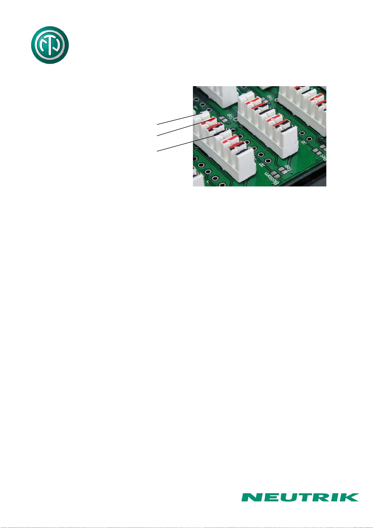
Color coding of terminals:
white - sleeve (shield)
red - tip (Signal +)
black - ring (Signal -)
The terminal handles solid cables AWG 26 to 20.
Wire (conductor) diameter Wires per slot
≥ 0.40 mm ≤0.65 mm 2
≥ 0.65 mm ≤0.90 mm 1
When using wire in the range of 0.4 to 0.65mm diameter, the modules allow up to two identical
wires of the same diameter to be terminated in one contact. It is not possible to use 2 wires of
differing diameter.
Terminations with stranded wire range
No of strands Diameter of each wire strand Nominal insulated diameter
7 0.15 mm (AWG 34) 1.10 mm
7 0.20 mm (AWG 32) 1.20 mm

Page 7 of 11
NPPA-TT-IDC Instruction Manual
4. Cable retention
The built in cable retention bar is at the back at the casing. Simply attach the cables with cable
ties to the bar as shown on the photo.
For large and heavy bundles there is an additional strain relief bar NPPA-S available. It is
attached to the casing with four screws.
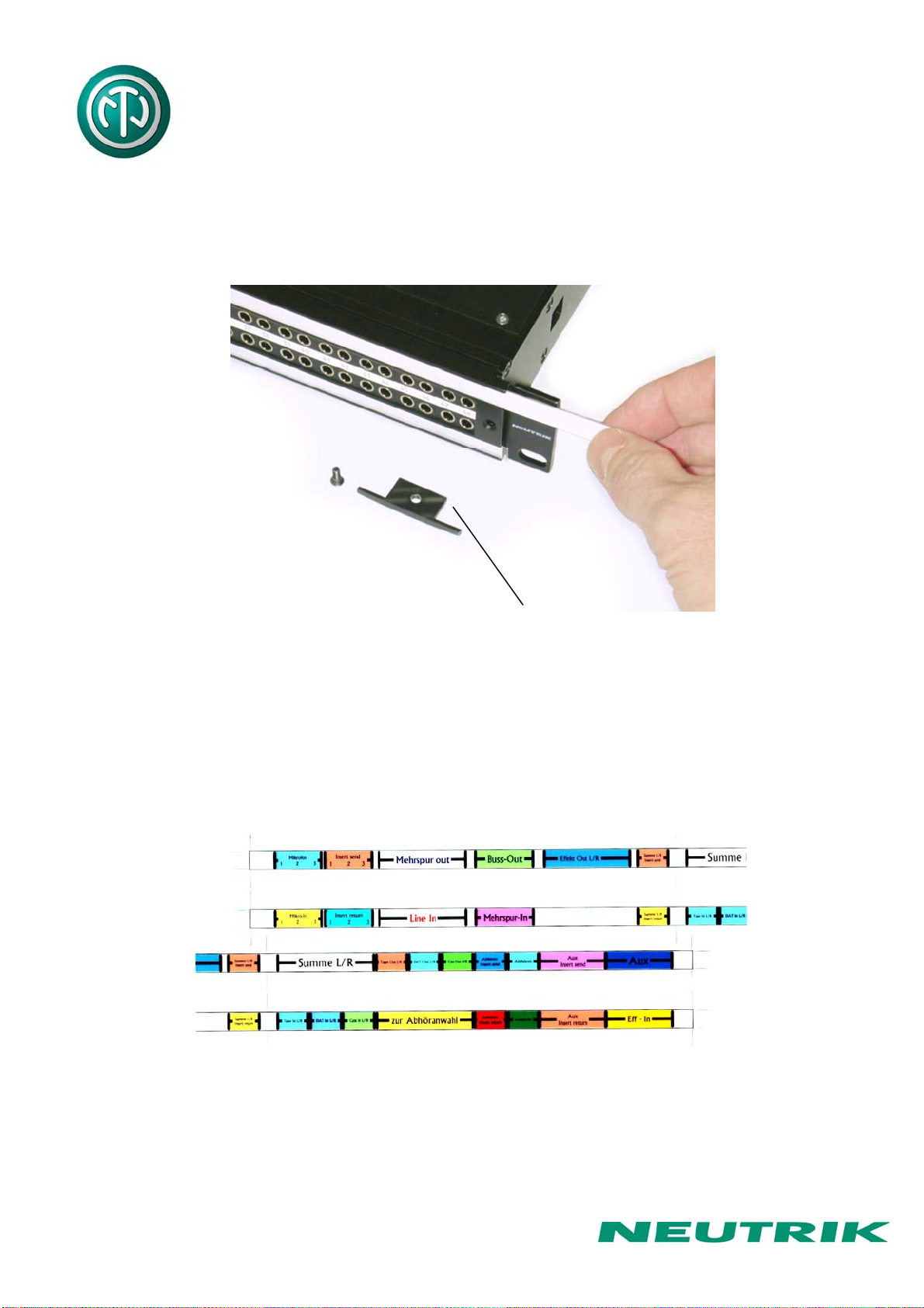
5. Channel identification
The front panel is equipped with channel identification strips located in the center of the
channels and marked with the channel numbers 1-24 and 25-48 respectively.
Channel identification strips Labeling strips
For the perfect management of the system and for individual identification according to
customer’s needs there are two large and separate labeling strips, one for the bottom and one
for the top row.
Page 8 of 11
NPPA-TT-IDC Instruction Manual
To write on the paper you have to unscrew one of the outer fixing screws of the front panel.
Then pull out the side-stop, the transparent foil and the paper strip itself.
After marking is done assemble the parts in reversed sequence.
Remove labeling strip Side Stop
NOTE: For easy and perfect marking you can use our designation software “PatchLabel”
which is available on our web site www.neutrik.com free of charge.
Print-Out software “Patch Label”
Page 9 of 11
NPPA-TT-IDC Instruction Manual
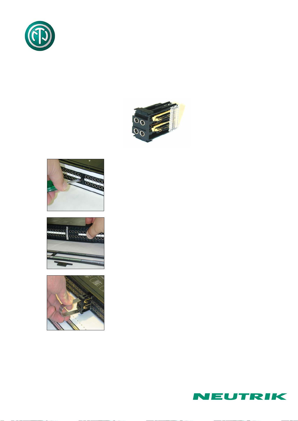
6. Replacement of Jack Pairs
Each individual jack pair can be exchanged quickly and without fuss even while the panel is "on
air". For replacement simply remove the easy accessible jack pairs.
Module consisting of 2 Jack Pairs
Remove Front Panel by unscrewing the 3 black cross-
recessed screws (M3x8 Taptite), remove the two side-
stops.
Push out the channel identification strips.
Pull one module out of the casing using the supplied
disassembling pliers

Page 10 of 11
NPPA-TT-IDC Instruction Manual
Alternatively the jack pairs may be pulled out by the use of
two Bantam plugs (diagonally plugged in).
The two jack pairs have to be re-assembled in the right way
so that the thicker body marked “left” is put on the left side
with the mark outside and readable.
To complete, push the new jack pairs into the casing again with the mark on the left side (If
more than one module are removed always assemble from the center to the right or left side
and be careful that the keys on the left side of the jack pairs find their guiding slots. If all jack
pairs are removed start at the casing support in the center and assemble to the right and left
side). Slide in again the channel identification strips (best from the outside inwards) and fix the
front panel with the black cross-recessed screws. Don’t forget to insert the side-stops before
fixing the screws.
Indice


