select:
pick storeKWHr
ct KWHr pulse
Enter KWHr setup by pressing the button
to either “Store KWHr” to save and display
the accumulated watt hour value to flash
memory or “KWHr Pulse” to save and dis-
play accumulated value only while powered
on. Any change to the meter set-up will clear
the KWHr pulse.
Pressing “KWHr Pulse” before “Store
KWHr” will clear any previously ac-
cumulated watt hour value from flash
memory.
5-Amp Secondary CT
Ranges 333mV Secondary CT
Ranges
50 600 5 250
75 800 15 300
100 1000 30 400
150 1200 50 600
200 1500 70 800
250 1600 100 1000
300 2000 150 1200
400 2500 200 1500
500 3000
The APN can be used with many current trans-
formers, and it must be programmed for the
range you will be using. The ranges available
are:
Next select the rate at which the pulse con-
tact opens and closes. The options are 1/10,
1, or 10 KWH per pulse. The solid state no
voltage contact will open and close when
the selected watt hours have accumulated.
Note: Only the 10KWHr setting is available
with CT ranges of 1000 or higher.
select: Save?
KWHr Yes NO
Once the pulse rate has been selected, the
display will change to show the selected
rate on the left. Pressing the button below
“Yes” will save this value to memory.
Pressing the button below “No” will return
you to the Power Up ID.
After completing the set up programming, the
LCD display can be changed to show several data
points. Press any button, and the display selection
screen will be seen.
select:
Energy PwrFtr VAWatt
Press the button below “Energy” and
the display will change to show the
following:
Energy
sumWatts 3,480
KWHr 127
PwrFtr +0.68
Sum Watts shows the active power
being used at any time.
KWHr increases as kilowatt hours are
accumulated.
Pwr Ftr shows the average power fac-
tor of all three phases.
This is generally the last screen viewed, and will be the default screen
shown. Press any button to return to set up or display other values.
select:
Energy PwrFtr VAWatt
Press the button below “PwrFtr” to
display the power factor of each phase
PowerFactor
A +0.70
B +0.71
C +0.68
The power factor is shown with a (+)
positive notation for inductive loads,
and a (-) notation for loads which are
capacitive.. If the monitored load is in-
ductive, all three phases should show
power factor as positive. If one or
more phases are displayed as “0.01”,
the current transformer is facing the
wrong direction or the leads are re-
versed (X1 connected to negative).
select:
Energy PwrFtr VAWatt
Press the button below “VAWatt” to
display the voltage, current and watts
of each phase.
Volts Amps Watts
128.8 27.5 2871
129.7 28.5 2997
127.8 27.5 2749
About MODBUS and the APN Power Monitor
MODBUS® Protocol is a messaging structure, widely
used to establish master-slave communication between
intelligent devices. A MODBUS message sent from a
master to a slave contains the address of the slave, the
‘command’(e.g. ‘read register’), the data, and a check
sum (CRC). Since MODBUS protocol is just a messag-
ing structure, it is independent of the underlying physical
layer. The interface used by the Monitor is RS-485.
The Query
The function code in the query tells the addressed slave
device what kind of action to perform. The data bytes
contains any additional information that the slave will
need to perform the function. Only function code 03 HEX
(Read Holding Registers) is supported by the Monitor,
other codes will not be responded to and the red FAULT
LED will turn on. The Monitor will read the requested
registers and return their values. The data field will con-
tain the information telling the slave which registers to
read. The error check field (CRC) provides a method for
the slave to validate the integrity of the message contents.
The Response
If the slave detects a transmission error, the message
will not be acted upon, but the red FAULT LED will be
turned on. If the slave makes a normal response, the func-
tion code in the response is an echo of the function code
in the query. The data bytes contain the data collected by
the slave, with the reading of voltage, current, Watts and
Power Factor.
If an out of bounds register is requested , no register
or too many registers have been requested, the function
code is modified by adding 80 HEX to the function code
(returning 83 HEX) to indicate that the response is an
error response. There also will be 2 data bytes of zeros
returned. The error check field (CRC) allows the master to
confirm that the message contents are valid.
RTU Mode
When controllers are setup to communicate on a MOD-
BUS network using Remote Terminal Unit (RTU) mode,
each eight-bit byte in a message contains two four-bit
hexadecimal characters. Each message is transmitted in a
continuous stream.
Coding System
Consists of eight-bit binary, hexadecimal 0 ... 9, A ... F.
There are two hexadecimal (HEX) characters contained in
each eight-bit field of the message
Bits per Byte:
1 start bit
select:
10/KWH next 1/KWH
Press the button below the value you have
selected, or next to see other values.
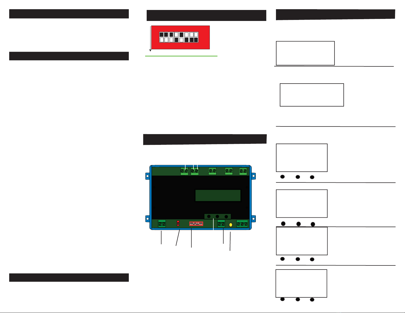
Pulse Contact Connection
DC Power Source
Out to Controller 10K Pull Up Resistor
Use an external resistor
of 10K ohm from the DC
power to the pulse output
contact (+) and out to the
controller input. Ground
the (-) terminal of the pulse
contact. This will allow volt-
age to pass when the output
is open, and block when
closed. One kwh value is
represented with an open and
closed output cycle.
-+