NSI I/F 501 Istruzioni operative

I/F 501
INTERFACE UNIT
INSTALLATION AND OPERATION GUIDE
Software Revision 1.05, Version A
INTRODUCTION
The I/F 501 interface unit allows a variety of comunication protocals used in NSI and other industrial equipment
to be translated between one another. In addition the I/F 501 can serve as an independent, programmable lighting
controller. The I/F 501 also serves as the interface between NSI’s Luma-net network and a personal computer.
SPECIFICATIONS:
Microplex Input (I/O) 3 pin XLR male
Microplex Ouput (I/O) 3 pin XLR female
DMX 512 Input 5 pin XLR male (USITT spec)
DMX 512 Output 5 pin XLR female (USITT spec)
AMX 192 Output (optional, replaces 512) 4 pin XLR female (USITT spec)
RS-232 I/O 9 pin ‘‘D’’ connector
MIDI input / Analog input 5 pin din 180 degree connector
Luma-net I/O Modular style telephone connector
Power requirements +15VDC 200ma (power supply included)
IMPORTANT
Although many different connectors are present on this unit, in most configurations, one or more of the connectors
may serve no function. It is important that the installer verify that the required inputs and outputs operated in the
mode required for the application. Please read the appropriate application sheets in this manual carefully before
installing.

Front Panel
1DC Power input - Connect 15VDC (+ tip, - ring) 250ma here. (Supplied with unit.)
2Address - Controls translation of adresses (and other special functions). See individual applications details.
3Config - Determines the operating mode of the unit.
4PWR - Indicates presence of +15VDC
5STAT - Usually indicates presence of input signal.
6ERR - Indicates an input signal error.
7MIDI/ANALOG - Midi input or analog input depending on application.
8LUMA-NET I/O - Connects to a Luma-net network.
9RS-232 - Connects to a personal computer.
Rear Panel
1MICROPLEX IN - Input Microplex here. Also may serve as pass- through I/O in some applications.
2MICROPLEX OUT - Output Microplex here. Also may serve as pass-through I/O in some applications.
3DMX 512 IN - Input DMX 512 here.
4DMX 512 (AMX 192) OUT - Output DMX 512 here (or optionally AMX 192).
INTERFACE UNIT
Software Revision 1.05, Version A Front Panel
NSI CORPORATION 2

JUMPER LOCATIONS
PCB locations of jumpers / internal connectors
INTERFACE UNIT
Software Revision 1.05, Version A JUMPER LOCATIONS
NSI CORPORATION 3
INPUT -> OUTPUT CONFIG
SWITCH
d-down
u-up
1234
P4
P5 P7 JP1 JP6
JP7 JP8
JP9 JP10 JP11 JP12 DMX
OUT
CONN
DEFAULT SETTINGS dddd OFF ON 62-3 2-3 2-3 2-3 1-2 JP4
MPX -> DMX dddd
MPX -> AMX uddd OFF JP3
DMX -> MPX dudd ON
MIDI -> MPX/DMX uudd 2 1-2 1-2 2-3
MIDI -> AMX ddud OFF 21-2 1-2 2-3 JP3
RS-232 -> MPX/DMX udud 1-2
RS-232 -> AMX duud OFF 1-2 JP3
LUMANET/MPX/DMX -> MPX uuud ON 2
LUMANET/MPX -> DMX dddu 2
LUMANET/MPX -> AMX uddu OFF 2JP3
MPX/DMX/ANALOG -> MPX/DMX dudu
MPX/DMX/ANALOG -> AMX uudu OFF JP3
AUTO-CHASE -> MPX dduu
RS-232 AUTO-CUEING -> MPX/DMX uduu 1-2 1-2
IF-501 (AS 404CP) -> LUMANET duuu 1-2 1-2
RS-232 -> LUMANET uuuu 1-2 1-2
Set to default settings, then change as indicated for specific mode.
I/F 501 JUMPER CHANGE QUICK REFERENCE CHART
MPX = N.S.I. Microplex
DMX = DMX-512
MIDI = Musical Instrument Digital Interface
AMX = AMX-192
RS-232 = RS-232C Serial data protocol
LUMANET = N.S.I. Lumanet architectural protocol
ANALOG = 0 - 10 VDC continuous voltage control
IF-501 = N.S.I. protocol translator / controller
404CP = N.S.I. architectural control panel
JP13 = 2-3
P6 = OFF (no termination)
or ON to terminate DMX lines
P8 = OFF (no termination)
or ON to terminate Lumanet lines
INTERFACE UNIT
Software Revision 1.05, Version A JUMPER LOCATIONS
NSI CORPORATION 4

PINOUTS
Pinouts of the various connectors
INTERFACE UNIT
Software Revision 1.05, Version A PINOUTS
NSI CORPORATION 5
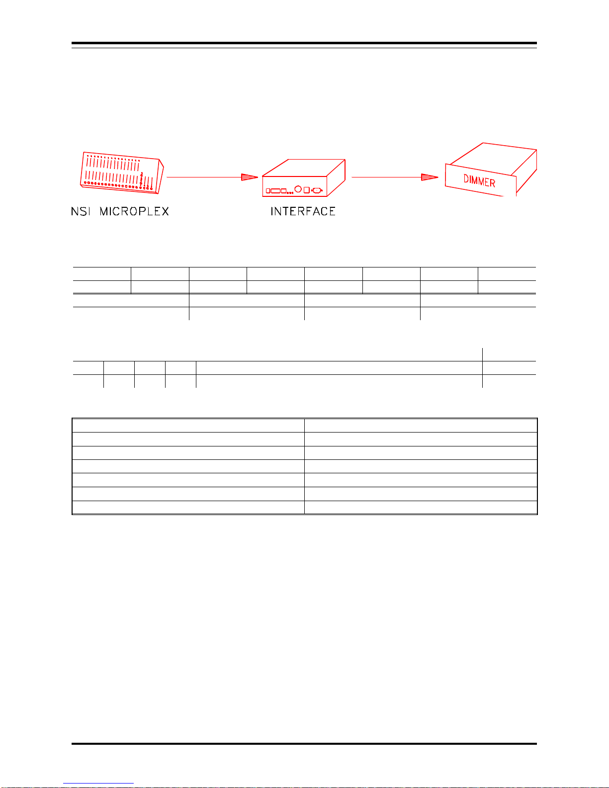
MICROPLEX TO DMX 512
In this application, Microplex is converted to DMX-512. The Microplex is then retransmitted.
CONNECTOR OPERATION
Microplex IN Input Microplex
Microplex OUT Retransmitting Microplex (64 or 128)
DMX IN Not used
DMX out Output DMX 512
MIDI / Analog Not used
Luma-net Not Used
RS-232 Not Used
JUMPER LOCATIONS
P4 & 5 P7 JP6 & 7 JP8 & 9 JP10 JP11 JP12 JP13
OPEN CLOSED N/A N/A 2-3 2-3 N/A 2-3
P6 P8 JP1 DMX OUT CABLE
N/A N/A N/A JP4
DIPSWITCH POSITIONS
C1 C2 C3 C4 ADDRESS 1 - 7 A8
DN DN DN DN NOT USED DN:64
Microplex is converted channel to channel so address is not used.
DMX output is sent as either 64 or 128 channels, depending on the setting of switch A8.
INTERFACE UNIT
Software Revision 1.05, Version A MICROPLEX TO DMX 512
NSI CORPORATION 6

MICROPLEX TO AMX 192
In this application, Microplex is converted to AMX-192. The 5 pin XLR may be replaced with a 4 pin XLR
(USITT) if desired.
CONNECTOR OPERATION
Microplex IN Input Microplex
Microplex OUT Not Used
DMX IN Not used
*DMX out Output AMX 192 (64 or 128 channels)
MIDI / Analog Not used
Luma-net Not Used
RS-232 Not Used
JUMPER LOCATIONS
P4 & 5 P7 JP6 & 7 JP8 & 9 JP10 JP11 JP12 JP13
OPEN OPEN N/A N/A 2-3 2-3 N/A 2-3
P6 P8 JP1 DMX OUT CABLE
N/A N/A N/A JP3
DIPSWITCH POSITIONS
C1 C2 C3 C4 ADDRESS 1 - 7 A8
UP DN DN DN N/A DN:64
Microplex is converted channel to channel so address is not used.
AMX output is sent as either 64 or 128 channels, depending on the setting of switch A8.
*IMPORTANT - Move AMX output connector jumper from JP4 to JP3.
INTERFACE UNIT
Software Revision 1.05, Version A MICROPLEX TO AMX 192
NSI CORPORATION 7
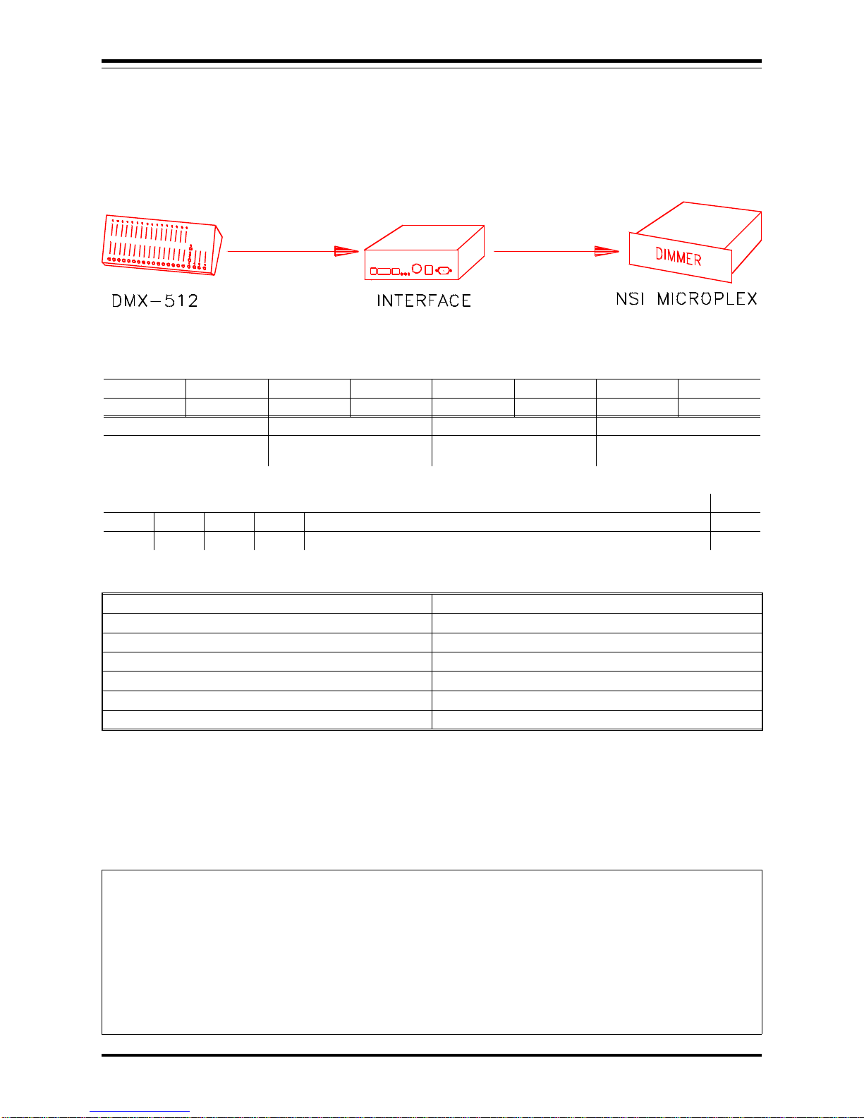
DMX 512 TO MICROPLEX
In this application, DMX 512 is converted to Microplex..
CONNECTOR OPERATION
Microplex IN Not used
Microplex OUT Output Microplex (64 or 128)
DMX IN Input DMX 512
DMX out Pass through DMX 512
MIDI / Analog Not used
Luma-net Not Used
RS-232 Not Used
JUMPER LOCATIONS
P4 & 5 P7 JP6 & 7 JP8 & 9 JP10 JP11 JP12 JP13
CLOSED CLOSED N/A N/A 2-3 2-3 N/A 2-3
P6 P8 JP1 DMX OUT CABLE
*CLOSE TO TERM
DMX N/A N/A JP4
DIPSWITCH POSITIONS
C1 C2 C3 C4 ADDRESS 1 - 7 A8
DN UP DN DN STARTING DMX CHANNEL FOR MICROPLEX BY 16 INCR. DN:64
Microplex channel 1 is equal to starting DMX channel. Address switch 1 - 6 sets starting DMX channel in
increments of 16. See chart at the end of this manual.
Microplex output is sent as either 64 or 128 channels, depending on the setting of switch A8.
*DMX should only be terminated internally if IF501 will be always last unit at end of DMX line. A better way
to terminate is to connect 120ohm resistor to a female DMX cable end (pins 2-3) and plug it into the pass-through
of the last unit on the DMX line.
INTERFACE UNIT
Software Revision 1.05, Version A DMX 512 TO MICROPLEX
NSI CORPORATION 8
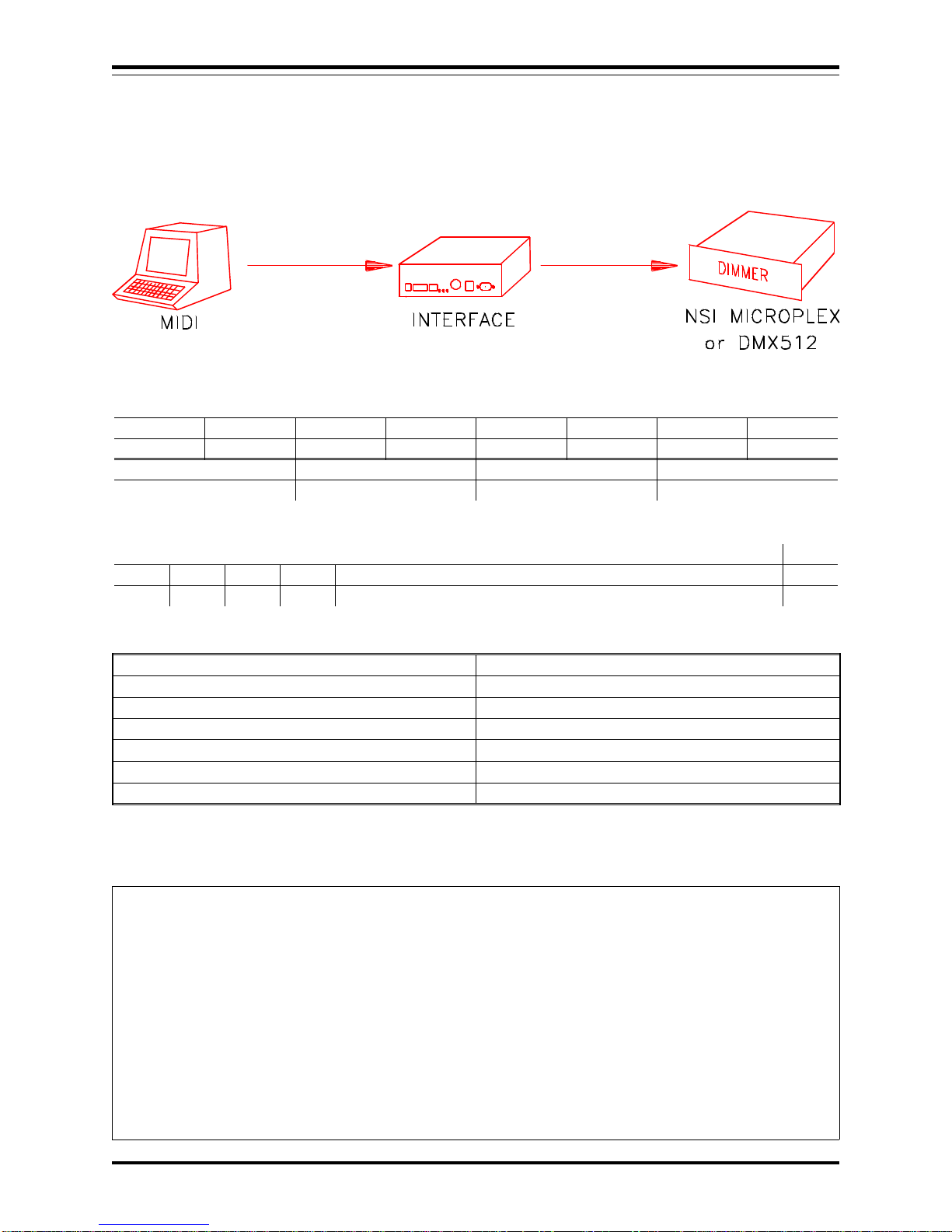
MIDI TO MICROPLEX and DMX 512
In this application, MIDI note commands are converted to Microplex and DMX 512 dimmer levels.
CONNECTOR OPERATION
Microplex IN Not Used
Microplex OUT Output Microplex (64 or 128)
DMX IN Not Used
DMX out Output DMX 512
MIDI / Analog Input MIDI
Luma-net Not Used
RS-232 Not Used
JUMPER LOCATIONS
P4 & 5 P7 JP6 & 7 JP8 & 9 JP10 JP11 JP12 JP13
OPEN CLOSED N/A 1-2 1-2 2-3 2-3 2-3
P6 P8 JP1 DMX OUT CABLE
N/A N/A POSITION 2 JP4
DIPSWITCH POSITIONS
C1 C2 C3 C4 ADDRESS 1 - 7 A8
UP UP DN DN A1-4 SELECTS MIDI CHAN, 5 UP SETS IGNORE NTOFF DN:64
MIDI Channel 1 - 16 can be selected with switch A1-4 (see chart at end).
Velocity of MIDI Note On messages set respective dimmer levels. C0 = dimmer channel 1.
Note Off (or Note On = 0) will turn off channel unless A5 is in the up position.
DMX or Microplex output is sent as either 64 or 128 channels, depending on the setting of switch A8.
INTERFACE UNIT
Software Revision 1.05, Version A MIDI TO MICROPLEX and DMX 512
NSI CORPORATION 9

MIDI TO AMX-192
In this application, MIDI is converted to AMX 192.
CONNECTOR OPERATION
Microplex IN Not used
Microplex OUT Not Used
DMX IN Not used
*DMX out Output AMX 192 (64 or 128 ch)
MIDI / Analog MIDI Input
Luma-net Not Used
RS-232 Not Used
JUMPER LOCATIONS
P4 & 5 P7 JP6 & 7 JP8 & 9 JP10 JP11 JP12 JP13
OPEN OPEN N/A 1-2 1-2 2-3 2-3 2-3
P6 P8 JP1 DMX OUT CABLE
N/A N/A POSITION 2 JP3
DIPSWITCH POSITIONS
C1 C2 C3 C4 ADDRESS 1 - 7 A8
DN DN UP DN A1-4 SELECTS MIDI CHAN, A5 UP SETS IGNORE NTOFF DN:64
MIDI Channel 1 - 16 can be selected with switch A1-4 (see chart at end).
Velocity of MIDI Note On messages set respective dimmer levels. C0 = dimmer channel 1.
Note Off (or Note On = 0) will turn off channel unless A5 is in the up position.
AMX output is sent as either 64 or 128 channels, depending on the setting of switch A8.
*IMPORTANT - Move AMX output connector jumper from JP4 to JP3.
INTERFACE UNIT
Software Revision 1.05, Version A MIDI TO AMX-192
NSI CORPORATION 10
Indice
Manuali Apparecchiature di registrazione popolari di altre marche


Strymon
Strymon NIGHTSKY Manuale utente

Mitsubishi Electric
Mitsubishi Electric 16CH DIGITAL RECORDER DX-TL5000U Manuale utente

Tews Technologies
Tews Technologies TPMC465 Manuale utente

Honeywell
Honeywell Excel 50 Manuale utente

SeaLevel
SeaLevel COMM+8.LPCI Manuale utente

Arturia
Arturia AUDIOFUSE STUDIO Manuale utente


