Quick Installation Guide
2.3 Connecting to the Website
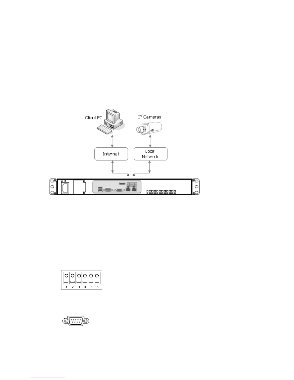
The Network Video Recorder supports the operation through the network. When the NVR is first connected to
the network, it has no IP address. So, it is necessary to allocate an IP address to the device with the “Smart
Manager” utility on the CD.
Note: Factory Default IP address is 192.168.100.220
1. Start a browser (Internet Explorer).
2. Enter the IP address or host name of the Network Video Recorder in the Location/Address field of your
browser. The NVR2 installs and executes the client software automatically after installing ActiveX.
3. If the NVR has not been configured, Setup Wizard will be shown. This drastically reduces the time
required for system installation. Images from cameras are connected and recorded automatically to the
NVR, so that you can start monitoring and recording instantly.
Note: Setup Wizard will be shown only in factory default state.
Follow the instructions of the wizard to complete the system setup.
[Step1]
Enter the date and time settings. You can select to synchronize the server time with an internet time
server. If you enter a domain name for the NTP server, make sure you have set up a correct DNS server.
Click the Next button to go to next page.
8