NTI Caprice C95-BF Manuale del proprietario

Installation and Maintenance instructions
Supplemental Instructions
For
Caprice (Balanced Flue)
Save these instructions

1.0 SETTINGS & TECHNICAL DATA
RIELLO BURNER
Input Nozzle Pump Output Burner Settings
Model gph 60°B (psig) MTUH EFF. Model Air Turbulator
C95-BF 0.75 0.65 135 93 89.0% BF5 4-1/4 0
C105-BF 0.85 0.75 130 104 87.8% BF5 5-1/2 0
C125-BF 1.00 0.85 140 123 88.2% BF5 4 0
C150-BF 1.25 1.00 155 150 86.0% BF5 6 1
BECKETT BURNER
Input Nozzle Pump Output Burner Settings
Model gph 60°B (psig) MTUH EFF. Head Air Pin
C95-BF 0.75 0.65 135 93 89.0% NYC804 4.5 1
C105-BF 0.85 0.75 130 104 87.8% NYC804 6.0 2
C125-BF 1.00 0.85 140 123 88.2% NYC803 3.5 2
C150-BF 1.25 1.00 155 150 86.0% NYC803 5.5 5
NOTE: Model C95 and C105 with the NYC 803 Beckett comes with a AF2-6 head
and the other models with type AF2-9 head and 5” insertion.
Draft settings- Due to the design of the balanced flue system, the Caprice will operate at a
positive draft pressure and a positive over fire pressure at all times. It is design to operate with
a maximum stack draft of 0.25” W.C and a maximum over fire draft of 0.33” W.C. when little or
no wind is present. In extreme wind conditions, the maximum stack draft is 0.35” W.C. and the
maximum over fire draft is 0.45” W.C. .
2.0 INSTALLATION COMPONENTS
Following is a list of the parts included in the balance flue kits with their part numbers.
PART # DESCRIPTION
81112 6” TO 3” PORTED ADAPTER
? 3” FLEX TO PIPE ADAPTOR
81114 DIRECT VENT TERMINAL
81123 4” TO 3” INCREASER (BECKETT ONLY)
81124 3000 ΩRESISTOR
3” FLEX x 10’
PART # DESCRIPTION
81111 20 FEET INSULATED FLEX
81110 15 FEET INSULATED FLEX
81097 10 FEET INSULATED FLEX
81109 5 FEET INSULATED FLEX
The insulated flex section for the exhaust
has to be ordered separately.
Contents of Vent kit

3.0 INSTALLATION CODES
Install the balanced flue
system according to
CSA S139 codes to
ensure a safe operation
of your unit.
The following guidelines
are included in the CSA
codes and must be
respected at all times:
A) Use approved
venting components
only.
B) The vent and air
intake maximum
length is 20 ft (6 m)
C) The vent must be in
one continuous
piece with no joints.
D) Combustion air
intake and the vent
must be installed on
the same wall to
ensure that the
system is balanced.
E) Vent terminal shall not terminate:
• closer than 6 ft (1.8 m) from the property line
• any closer than 6 ft (1.8 m) from another NY Thermal vent terminal or combustion air inlet
for any other appliance .
• Above a gas meter/regulator assembly within 3 ft. (0.9m) horizontally of the vertical
centerline of the regulator.
• any closer than 6 ft (1.8 m) of any gas service regulator vent outlet
• Above a paved sidewalk or a paved driveway if the following serves two buildings and is
located between them.
• Any closer than 7 ft (2.13 m) above any paved sidewalk or paved driveway.
• Any closer than 3-ft (0.9 m) of an oil tank vent or an oil tank inlet.
• Any closer than 6-ft (1.8 m) of a door, window, another NY Thermal vent terminal or
mechanical air supply inlet to any building (includes soffit openings).
• In a location where the flue gases are directed at combustible material that are within 6-ft
(1.8 m).
• With the bottom of the vent termination opening less than 1-ft (0.3 m) above any surface
that may support snow, ice, or debris.
• With its flue gases directed towards siding, brickwork, or other construction, in such a way
that may cause damage from heat or condensate from the flue gases.

• Within 1 ft (0.3 m) above grade (ground or any surface that will support snow).
• underneath a deck, porch, or veranda
• closer than 6 ft (1.8 m) from an inside corner of an L-shaped structure
• In a location where the flue gases are directed at any opening of surrounding buildings
that are within 6-ft (1.8 m).
See instruction sheet NYT.2V-2.0 for multiple vent terminal arrays.
NOTE: Even if all the installation codes are met, good judgement and common sense must
also be used for selecting an appropriate location for the balanced flue intake and outlet.
4.0 Venter Installation Steps
1. Select a suitable location for the vent terminal, It is
highly recommended that the vent terminal be
located where it will not be exposed to normal
prevailing winds. See the back of this sheet for code
restrictions.
NOTE: Under normal operating conditions
this appliance will produce a plume of white
gases, and should be taken into
consideration when selecting an adequate location.
2. Ensure that the outside wall surface is flat and meets the installation restrictions.
3. Cut a rectangular hole, 5.5” wide, and 6” in height.
4. Insert the vent terminal through cut hole so that the 3” diameter hole at the back is
facing down.
5. Secure vent terminal to the side of the structure using 4- #10 stainless steel Screw.
6. Using a suitable silicone sealant, caulk the gap between the structure and the vent
terminal.
7. When installed correctly, the vent terminal pipe
should be pointing slightly uphill in order to
drain water to the outside.
8. Using a screwdriver, bend up the support bracket
located on the top of the unit as shown.
9. Support the back end of the vent terminal by
connecting the support bracket to a joist, or other
solid structure, by means of metal strapping or wire.
10. Using the screws provided, attach the air inlet
connection flange to the bottom of the vent terminal.

11. The back of the vent terminal is equipped with a flexible
heat shield, bend the flaps to the side, and then bend the
heat shield up, and out of the way.
12. Silicone caulk the space between the vent terminal and
the structure.
13. Install the fresh air piping over vertical 3” end, and tighten
with a 3”gear clamp (not provided).
The boiler can now be connected to the exhaust terminal with the help of insulated flex piping.
The flex is available in lengths of 5 ft, 10 ft, 15ft, and 20 ft. Make sure that it’s long enough to
form long radius bends (no smaller than 1 ft in radius). If the flex is too long, it can be cut with
a hacksaw. Assemble pipe as detailed in Section 5.
5.0 CAULKING
WARNING THIS BALANCED FLUE SYSTEM WILL LEAK IF THE FOLLOWING
CAULKING PROCEDURES ARE NOT FOLLOWED. IT’S EASIER TO SEAL THE ENTIRE
SYSTEM PROPERLY THE FIRST TIME THAN RETURN AT A LATER DATE AND HAVE TO
REMOVE THE CONNECTIONS TO RESEAL IT.
The caulking instructions are included in the installation section, but this section has
more details
NOTE: - The adapters are multi-start, left hand thread, with one thread twice the width of the
others. Therefore, care must be taken to ensure that the correct threads are engaged before
tightening in a counter clockwise direction.
The vent must have 9” clearance to combustible within 36” of the appliance breech.
The remaining section of the vent to the terminal can have a minimum of 1” clearance.
The terminal is rated for 0” clearance.
Because the balanced flue system operates with a positive pressure in the exhaust at all times,
the caulking has to be done properly to prevent leaks at the joints. The type of caulking used

throughout this installation is critical to the operation of the balanced flue system. A tube of
caulking is provided with the installation kit. This tube should be sufficient for the whole
installation, but if more caulking is needed buy one of the following: GE 106, Dow Corning 736
Heat Resistant Sealant, Perimeter 248 High Temp or RTV Silicone Gasket.
Follow these steps to obtain a good seal.
Boiler
A. Seal the 6” smoke collar to the smoke hood on the boiler with the high temperature
silicone. Inspect all boiler openings (sight door, burner connection, pipe joints, Etc) during
initial operation, to verify that there are no leaks.
Flex Pipe
Make sure that it’s long enough to form long radius bends (no smaller than 1 ft in radius). If the
flex is too long, it can be cut with a hacksaw.
It is recommended to remove the collar on the 81098 & 81112 flex adapters that secures
the insulation and outer foil of the Flex pipe. This can be accomplished by removing the
pop rivet at the base of the collar, and backing off the gear clamp completely. After
removing the collar, you will get a perfect unobstructed view of the pipe joint. To
reinstall, put the collar back into place and install a #8x½” screw in rivet hole, and re-
thread the gear clamp.
B. Pull the outer foil sheathing and insulation back as far as possible, to give an unobstructed
view of the pipe joints. Put 1 bead of silicone on both inside ends of the insulated flex pipe,
approximately 1” wide and ½” from the end. Put 1 bead of silicone on both outside ends of
81098 & 81112 connectors, approximately 1” wide and 1” from the bottom of the threads.
Screw in part number 81089 & 81112 adapters into the insulated flex and pull the
insulation and the outside flex over the collar and tighten the gear clamp.
C. Apply a wide bead on top of the flex joint.
D. Reinstall the collars on the vent connectors using a #8x½” screw in rivet hole, and re-
thread the gear clamp
E. Apply silicone between the vertical overlap joint of the 6-3” adapter.
F. Apply silicone on inside surface of the 6-3” adapter
G. Apply silicone on outside surface of the smoke hood collar, and slide 6-3” adapter over the
smoke hood and tighten the gear clamp.
H. Perform steps D-G to install the 3” adapter #81098 over the 3” pipe of vent terminal, and
tighten gear clamp.
I. Fold the vent terminal heat shield flaps back into position.
NOTE: - It’s the installer’s responsibility to ensure that the combustion products do not enter
the home.
6.0 CLEANING
Do not remove the 6” to 3” adapter from the breech or any of the other exhaust connections for
cleaning the Caprice. Remove the top jacket panel and the flue cover with the adapter still
attach to it. Follow the typical boiler cleaning routine. To reattach the smoke hood, install ½”
ceramic rope under the smoke hood flange.

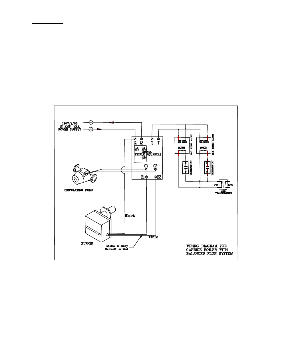
7.0 WIRING
All wiring must be in accordance with the Canadian Electrical code, CSA C22.2, and any local
codes that may become applicable. Insure that the wiring is in accordance with this manual.
The boiler must be electrically grounded in accordance with local codes, and C22.2.
Important Warning
It is the responsibility of the installer to ensure that:
• The boiler and venting system are totally sealed from products of combustion.
• The homeowner is advised of their responsibility of keeping the vent terminal clear
of snow and ice.
• That the home is equipped with a carbon monoxide sensor.

Questo manuale è adatto per i seguenti modelli
3
Indice
Altri manuali NTI Caldaia

NTI
NTI Trinity Ti 150 Manuale di servizio

NTI
NTI Trinity TX Series Manuale utente

NTI
NTI TFTN285 Manuale utente

NTI
NTI Lx150-800 Manuale utente

NTI
NTI Trinity Lx 500 Manuale utente

NTI
NTI Trinity TX51 Manuale utente

NTI
NTI WF200 Manuale utente

NTI
NTI FTG 600 Manuale utente

NTI
NTI TRINITY Ts80 Manuale utente

NTI
NTI FTG 2000 Manuale utente

NTI
NTI Matrix M100 Manuale utente

NTI
NTI FTVN085 Manuale di installazione

NTI
NTI C85-340 Manuale utente

NTI
NTI Tft60 - 399 Manuale utente

NTI
NTI TFTN 085-399 Manuale utente

NTI
NTI FTG 600 Manuale utente

NTI
NTI Matrix Manuale utente

NTI
NTI FTV110 Manuale utente

NTI
NTI VM110 Manuale utente

NTI
NTI TFTN Manuale utente