NXP Semiconductors K32L2B Manuale utente

1 Introduction
1.1 Overview
This document describes the hardware design of K32L2B Bluetooth Low
Energy (Bluetooth LE) Audio System and software architecture (top-level
design) of Host Controller (K32L2B). This document is provided for those who
intend to have a systematic view of K32L2B Bluetooth LE Audio System. They
can also refer to relevant ANs if need more introduction about Dongle (
K32L2B Dongle
), Headset (
K32L2B Headset
) and OTA
(
K32L2B OTA
).
•Hardware introduction introduces the hardware composition of K32L2B Dongle and Headset, as well as the connection
diagram.
•Software introduction introduces audio data path and software framework.
1.2 Summary
This document provides necessary information on how to get started on the K32L2B Bluetooth LE Audio System based on FRDM-
K32L2B board and NxH3670 SDK boards.
Figure 1. K32L2B + NxH3670 wireless headset use case
The system consists of a Dongle and a Headset, using K32L2B as Host Controller.
•Dongle: The Dongle has a USB interface that connects to PC. Dongle is responsible for setting up a wireless audio link
with Headset.
•Headset: The Headset has a speaker, a microphone and some User Interface (UI) components, such as, buttons, sliders,
rotary switches and LED. Headset is responsible for receiving audio data sent from Dongle and sending the recorded
audio to Dongle.
Contents
1 Introduction............................................ 1
2 Hardware introduction............................2
3 Software introduction............................. 5
4 Verification........................................... 11
5 Conclusion........................................... 14
AN12645
Getting Started with K32L2B + NxH3670 Gaming Use Case
Rev. 0 — 01/2020 Application Note

1.3 Reference documents
Table 1. References
Reference Definition
K32L2B Dongle
K32L2B USB Dongle with NXH3670
K32L2B Headset
K32L2B Headset with NXH3670
K32L2B OTA
K32L2B Bluetooth LE Audio System OTA operation steps
K32L2B Emulating the I2S Bus
Emulating the I2S bus master with the FlexIO module
2 Hardware introduction
2.1 System overview
Figure 2 shows the simplified system overview.
Figure 2. Simplified system overview
As shown in Figure 2, the audio transfer process include the folloiwng steps:
1. The NXH3670 boots up, starts and then communicates with K32L2B through the SPI interface.
2. Assuming NXH3670 can work well after Step 1, we use the USB interface to transfer audio stream from PC to host
controller. The 48 KHz USB audio is converted to an I2S signal, and then transmitted to NXH3670 of Dongle through the
I2S master emulated by FlexIO (
K32L2B Emulating the I2S Bus
) .
3. The audio stream can be transmitted to NXH3670 of Headset automatically. Users can hear voices with their headsets.
The current K32L2B Bluetooth LE Audio System includes FRDM-K32L2B board and NxH3670 SDK boards (KL27 Dongle and
Headset board to provide the basic Audio function respectively). This platform can:
• Send audio stream from PC to Headset.
• Receive control signal and recorded audio from Headset to PC.
• Update new firmware through Over The Air (OTA).
NXP Semiconductors
Hardware introduction
Getting Started with K32L2B + NxH3670 Gaming Use Case, Rev. 0, 01/2020
Application Note 2 / 15

Figure 3. K32L2B Bluetooth LE audio system hardware
As shown in Figure 3,
• In the Dongle part, the host controller is K32L2B and the Bluetooth LE device is NXH3670 on KL27 Dongle board. K32L2B
configures and communicates with NXH3670 through the SPI interface. K32L2B transfers audio data to NXH3670 through
the I2S bus emulated by FlexIO.
• In the Headset part, the host controller is K32L2B and the Bluetooth LE device is NXH3670 on KL27 Headset board.
K32L2B configures and communicates with NXH3670 through the SPI interface and configures CODEC using the I2C
interface.
2.2 K32L2B Dongle
This section describes the current hardware design of K32L2B Dongle based on FRDM-K32L2B and KL27 Dongle board. Figure
4 shows the components and interfaces.
NXP Semiconductors
Hardware introduction
Getting Started with K32L2B + NxH3670 Gaming Use Case, Rev. 0, 01/2020
Application Note 3 / 15

Figure 4. K32L2B Dongle hardware design
User can use a USB cable to connect J13 (FRDM-K32L2B) with PC to power or download firmware.
2.3 Headset
This section describes the current hardware design of K32L2B Headset based on FRDM-K32L2B and KL27 Headset board.
Figure 5 shows the components and interfaces.
Figure 5. Headset hardware design
NXP Semiconductors
Hardware introduction
Getting Started with K32L2B + NxH3670 Gaming Use Case, Rev. 0, 01/2020
Application Note 4 / 15
• In the Headset design, we use I2C interface to configure CODEC.
• The NXH3670 communicates with CODEC using I2S (as shown in Figure 5, the attached jumpers of 9-10,
11-12, and 13-14 indicate that they can transfer data directly without the extra operation of K32L2B.
• User must make sure the existence of jumper 9-10 (J10 CLK_SELECT, the yellow jumper OSC_MCLK
(12.288 MHz) in Figure 5), as it is used to obtain 12.288 MHz frequency and then can provide 24.576 MHz
frequency to I2S_MCLK.
NOTE
3 Software introduction
3.1 Audio path
The Bluetooth LE Audio System consists of two channels:
1. The forward-channel transmits the audio from the PC to the Headset.
2. The backward-channel transmits the microphone signal from the Headset to the PC.
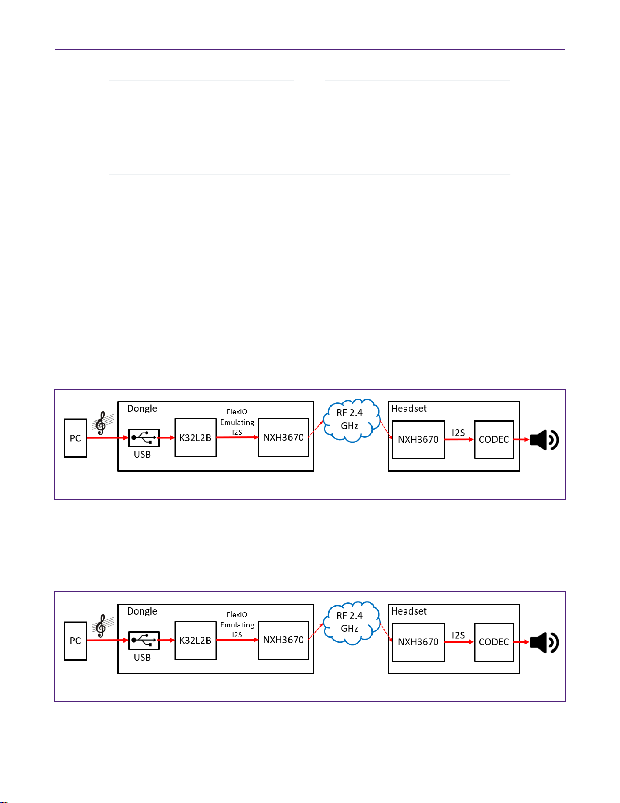
3.1.1 Forward audio channel
• The forward-channel is a stereo-channel.
• The RF transports the forward-channel as 16-bit samples @ 48 KHz sample-rate.
• The I2S bus emulated by FlexIO and USB signals uses 48 KHz sample-rate.
Figure 6. Data path of forward audio system
3.1.2 Backward audio channel
• The backward-channel is a mono-channel, only the left channel used.
• The RF transports the backward channel as 16-bit samples @ 16 KHz sample-rate.
• The I2S bus emulated by FlexIO and USB signals uses 48 KHz sample-rate.
Figure 7. Data path of backward audio system
NXP Semiconductors
Software introduction
Getting Started with K32L2B + NxH3670 Gaming Use Case, Rev. 0, 01/2020
Application Note 5 / 15

3.2 Application framework
The Application framework defines the software architecture of the reference application. The focus is modularity, code re-use
and software maintainability.
1. The top layer is Application Layer, which is strictly application specific.
2. The layer below is called Services Layer.
3. Underneath the Service Layer is Driver Layer which controls the hardware.
4. Board Support Package (BSP) contains the board-specific software, such as, hardware initialization, GPIO-pin
configuration, clock settings, etc.
Figure 8 shows the entire application architecture.
Figure 8. Application framework architecture
Users can design their own application or service on need. This document gives a brief introduction to the state machine that will
be used to control other services and the application.
Users can decide what service to perform in a state as they wish. For example,
• The state of an uninitialized USB-service is uninitialized, and then the state will change from Uninitialized to Stopped by
calling API initialize (&cfg) and executing successfully.
Figure 9 shows the mandatory API and corresponding state machine.
NXP Semiconductors
Software introduction
Getting Started with K32L2B + NxH3670 Gaming Use Case, Rev. 0, 01/2020
Application Note 6 / 15

Figure 9. Service state diagram
For example, the state can jump from Starting to Started by calling ReportState (Started).
FRAMEWORK_ServiceReportState (&g_XXXServiceApi, kSTATE_Started);
NXP Semiconductors
Software introduction
Getting Started with K32L2B + NxH3670 Gaming Use Case, Rev. 0, 01/2020
Application Note 7 / 15

3.3 Firmware development
3.3.1 Setting up the environment
This section introduces how to set up the MDK environment and the materials required in each step are described in Table 2.
Table 2. Materials required in Firmware development
List Description
PC Host device connected to the development board
Debugger • Default CMSIS-DAP firmware in the debugger onboard.
• Replace the default CMSIS-DAP firmware with J-LINK
firmware if user want to use JLink.exe to download Bin
file without IDE.
IDE MDK (V5.26.2.0)
Demos K32L2B+NxH3670.Zip for Gaming use case, including:
• Bin files that can be download through JLink.exe.
• Debug version of demo that can be used to re-
developed.
3.3.2 Software based on MDK
This document ports five demos:
• Dongle
• K32L2B_Headset
• K32L2B_OTA_Dongle
• K32L2B_OTA_Headset
• K32L2B_SSB
Figure 10 and Figure 11 list two demos as references for users if they want to port the demo to other boards.
NXP Semiconductors
Software introduction
Getting Started with K32L2B + NxH3670 Gaming Use Case, Rev. 0, 01/2020
Application Note 8 / 15

Figure 10. K32L2B Dongle project in MDK
NXP Semiconductors
Software introduction
Getting Started with K32L2B + NxH3670 Gaming Use Case, Rev. 0, 01/2020
Application Note 9 / 15

Figure 11. Headset project in MDK
If users want to use JLink.exe to download Bin file, make sure they have J-LINK firmware in Debugger onboard (MDK can be
used for checking), as shown in Figure 12.
Figure 12. JLINK firmware checking
The following files are required for users if they want to download Bin files from PC to K32L2B:
•J-LINK.exe
NXP Semiconductors
Software introduction
Getting Started with K32L2B + NxH3670 Gaming Use Case, Rev. 0, 01/2020
Application Note 10 / 15
Questo manuale è adatto per i seguenti modelli
1
Indice


