NZXT Hades Manuale utente

Hades
User’s manual


NZXT. 1
Thank you.
Dear valued customers,
Thank you for purchasing our product. We are thankful to all our fans
for the continuing support, after just four years since entering the computer
chassis market with the Guardian in 2003, NZXT is now an established gaming
brand and manufacturer of quality hardware in the market today. Since then, we
have stayed true to our goal, which was to continuously provide innovative next
generation products. With every product, we are still breaking more boundaries
and limits. Once again, thank you and all NZXT fans for the support and we hope
to bring more amazing products in the coming years.
After you complete your installation, please come by our community forums at
www.nzxt.com/forum and voice your opinions with thousands of NZXT fans from
around the world.
Sincerely,
NZXT Team

NZXT. 2
HADES Specifications
Expansion galore: Nine 5.25” bay setup or Five 5.25“ and Four 3.5”
Latest Hardware Support: VGA clearance room for 300mm cards like the ATI
5970
Dual 200mm intake Large air system: 200mm front fan, dual top 140mm fan,
Side 200mm fan, rear 120mm exhaust. NZXT includes the chassis with all fans
except for one top 140mm fan
Control the flow: Gaming, overclocking, or office work the dual 8W per channel
fan control allows control over the dual 200mm fans that spin up to 150 CFM
each
Monitor your system: A three C/F temperature display at front panel allows the
user to see temperatures inside the chassis even with the door closed. A slant on
the door allows for easier viewing from above
Punched side panel: Besides aesthetics, the side mesh and extrusion allows for
even greater and ease of wire management on the right side panel
Meshed front: 5.25” meshed bays, meshed door, and meshed bottom panel
allows for air to flow into the system with ease
Wire Routing: Motherboard punched holes allows for quick CPU bracket
removable and optimal wire routing
NZXT Solid State bracket allows for two SSD drives to be installed
Pre-drilled water cooling holes on the backplate
Front mounted 2 USB, Audio, and E-SATA ports
Mounting holes for dual radiator at the top
Removable filter at the bottom PSU
MOTHERBOARDS: ATX, MICRO ATX
DRIVE BAYS:
9 EXTERNAL 5.25” DRIVE BAYS
4 INTERNAL 3.5” HDD DRIVE BAYS and
5 EXTERNAL 5.25" DRIVE BAYS
7 Expansion Slots
COOLING FAN OPTIONS
Front, 1 x 200mm LED fan (Included)

NZXT. 3
Rear, 1 x 120mm fan (Included)
Side, 1 x 200mm fan (Included)
Top, 2 x 120/140mm fan (1 x 140 included)
CHASSIS
DIMENSIONS (D x W x H): 525 x 220 x 450 mm
CHASSIS MATERIAL: Steel
CHASSIS WEIGHT : 6.95 Kg
Table of Contents
Thank you. .............................................................................................................. 1
HADES Specifications ............................................................................................ 2
Before Beginning.. .................................................................................................. 3
Getting starting........................................................................................................ 3
Motherboard Installation......................................................................................... 4
LED, Power and Reset Installation......................................................................... 5
External 5.25” / 3.5” Drive Bay Installation.............................................................. 7
Internal 3.5” Drive Bay Installation.......................................................................... 9
Wire Routing and CPU fan bracket Removal........................................................ 10
PSU filter removal................................................................................................. 12
Dual channel 8W Fan controller............................................................................ 12
Three Temperature LCD display........................................................................... 13
Support and Service ............................................................................................. 13
Before Beginning..
For safety issues, it is highly recommended that all users wear gloves during
installation. Also, if you have any questions during installation, please send an
Getting starting
For users building a new system, it is recommended that the side panels are
removed before beginning the installation. The following steps will outline the
steps to remove the top, side panels and the motherboard tray.
NOTE: CPU, RAM and any peripheral installation are not
included in this manual. Please refer to your motherboard manual
for related mountin
g
instructions and troubleshootin
g
.

NZXT. 4
1. Remove the thumb screws securing the side panels.
2. Pull the side panel back, and then lift the panel to remove it.
Motherboard Installation
Please refer to the case interior infrastructure and secure the power supply at the
back of the case by using the screws provided.

NZXT. 5
1. Match the motherboard form factor ( ATX, M-ATX, ITX ) with the
holes on the motherboard tray
2. Secure the standoffs onto the holes which match your
motherboard
3. Lay the motherboard onto the standoffs and then continue to
secure the motherboard with the screws provided.
LED, Power and Reset Installation
Please refer first to your motherboard manual to locate where the power switch
and reset pins are located. The power switch is located on the door while the
reset button is located behind the door. The colors following each instruction
designate the color of the wires.
.
USB, Audio ports, and E-SATA
1. Connect the reset switch (labeled RESET SW) by connecting to your
motherboard RESET connector. Make sure you always attach the white
wire to ground. (Red/Black +/-)
2. Connect the power switch pin (labeled POWER SW) to the PWR
connector on the motherboard. (Brown/Black +/-)
3. Connect the HDD LED (labeled H.D.D LED) to the appropriate headers
on your motherboard. The HDD LED located on the front panel should
flash Blue when there is activity in the hard drive. (Blue/Black, +/-)
4. Connect the POWER LED(labeled +P LED/-P LED) to the appropriate
headers on your motherboard.(Green/Black,+/-)
All Black Pin Connectors correspond to ground.

NZXT. 6
USB Installation
1. The USB is located of the top on your front panel.
2. Refer to your motherboard manual and match the labels on the USB
port connectors with your motherboard in order to install.
Audio Port Installation
1. The NZXT Hades supports AC97 and Intel HD Audio, please connect
according to your motherboard specifications
2. Please first refer to your motherboard manual and match the labels on
the audio wires with your motherboard pins.
3. The green input is the speaker input and the pink input is the
microphone input.
Case Pins Signal Description ASUS© Pins
MIC-IN Front Microphone input Signal MIC2
MIC-POWER Front Microphone Power MICPWR
GROUND Front Audio Ground AGND
L-OUT Front Left Channel Audio Signal Line out_L
R-OUT Front Right Channel Audio Signal Line out_R
L-RET Rear Left Channel Audio Signal BLINE Line
out_L
R-RET Rear Right Channel Audio Signal BLINE Line
out_R

NZXT. 7
External 5.25” / 3.5” Drive Bay Installation
Please follow the directions below to install the 5.25” in the Hades chassis, follow
the same instructions for the 3.5” external bay:
1. Remove the front panel of the chassis by pulling from the opening at
the bottom of the front panel.
2. Remove the 5.25” black mesh for the 5.25” bay, by pushing the clips
aside
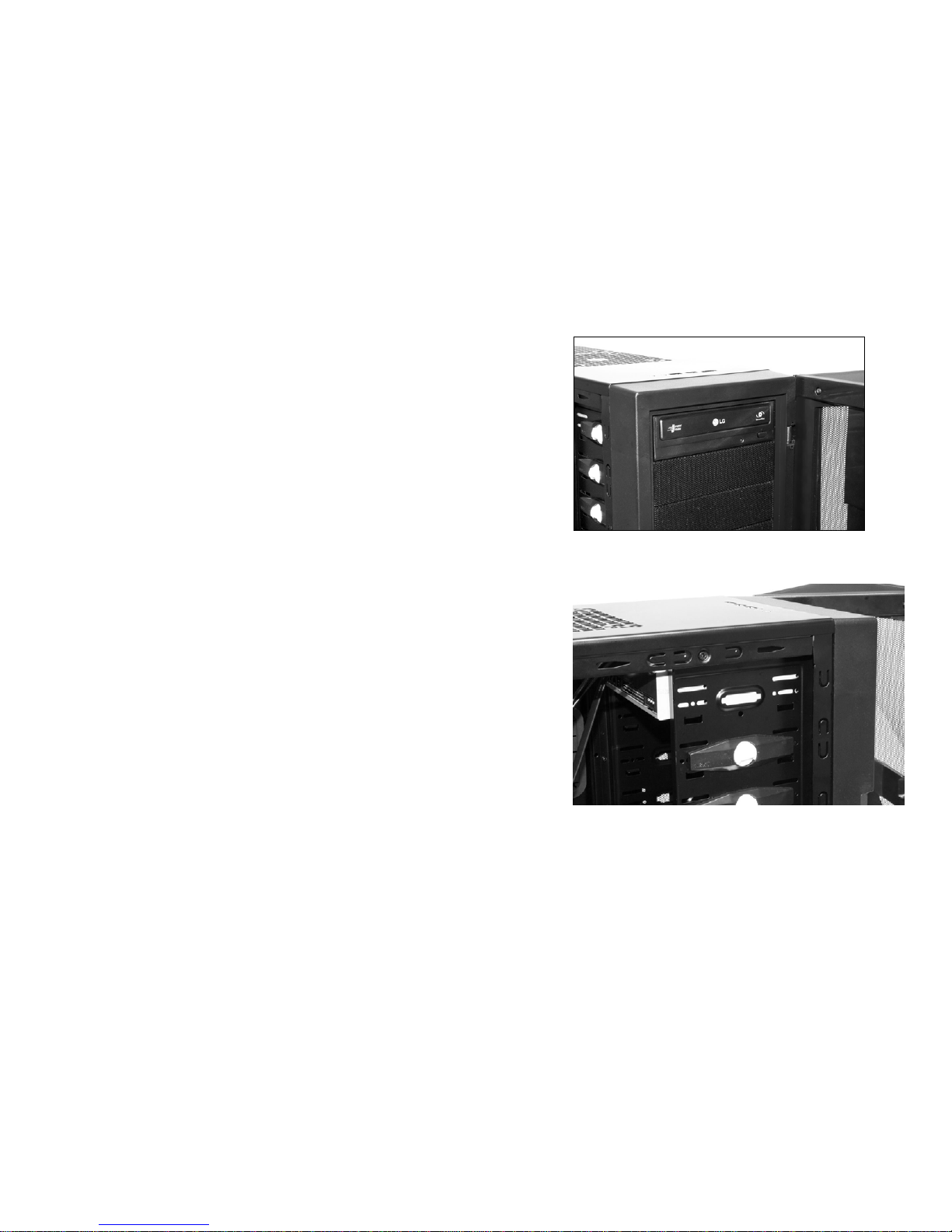
NZXT. 8
3. Slide the 5.25” drive in from the front of the
chassis
Insert the 5.25” Device through the 5.25” bay
4. Match the holes with the bay and the screw less bracket
Attach the screw less bracket matching the 5.25” holes
Indice
Altri manuali NZXT Allegato

NZXT
NZXT H400i Manuale utente

NZXT
NZXT Lexa S Manuale utente

NZXT
NZXT TEMPEST Manuale utente

NZXT
NZXT H5 FLOW Manuale utente

NZXT
NZXT H700i Manuale utente

NZXT
NZXT h440 Manuale utente

NZXT
NZXT Whisper Manuale utente

NZXT
NZXT H200i Manuale utente

NZXT
NZXT Phantom 410 Manuale utente

NZXT
NZXT GUARDIAN 921 Manuale utente


 Manuale utente")


