Oberhauser Bau-Systeme ISYS 1.1 Manuale utente

Installation Manual
Art.-Nr.: FRTSTV
Open Land System
ISYS 1.1

1
Thank you very much for choosing our mounting system.
With these instructions we will describe to you in detail how to proceed with the assembly.
If you have any questions, please do not hesitate to contact us at any time.
Content:
1. General Information 3
1.1 Designation of the individual parts 3
1.2 Overview of required tools and auxiliary materials 3
1.3 Tightening torques for screws 4
2. The Assembly 4
3. Theft protection 14
4. Maintenance 15
5. Surface treatment and corrosion 15
6. Safety and liability 16
6.1. Electrical Installation 16
6.2. Safety at work 16
6.3 Disclaimer 17

2
Dear Customer,
With the purchase of our systems you have not only secured technically mature products, but
also an excellent, complete service.
Our competent employees will advise you at any time if questions arise and will deal with your
request in detail and of course make sure that everything is carried out to your satisfaction.
Compared to conventional systems, our specially developed mounting systems have
significant, time-saving features that enable more efficient work when mounting the
substructure and modules!
If you do not want to deal with the installation yourself, simply request a quotation for the
installation of your project. We work together with the best installation companies worldwide
and can offer extremely economical conditions due to our many years of experience.
If you install your project yourself, we wish you success and hope that you were satisfied with
our service.
Your Oberhauser Team

3
1. General Information
•The soil conditions for the structures should be leveled and load-bearing.
•The electrical connection may only be carried out by a qualified electrician.
•The completed photovoltaic project should be completely surrounded by a fence
to protect it from unauthorized access or damage by wild animals.
•All packaging material must be disposed properly in accordance with legal and
technical regulations. See EN 378.
•The mounting systems from Oberhauser serve exclusively as substructure for
installing photovoltaic modules and may only be used in accordance with their
structural analysis.
•The photovoltaic modules may only be installed in accordance with the
manufacturer's instructions.
1.1 Designation of the individual parts
A = Ram profile C140 x 80 mm, Length according to requirements
B = Rafter profile C100 x 50 mm, Length according to requirements
C = Purlin C75 x 50 mm, Length according to requirements
D = Purlin connector
E = Hexagonal screw DIN 933 –M12 x 40, Material: A2-70 or 8.8
F = Washer DIN 9021 –13,0 mm; Material: A2 –70 or 8.8
G = Hexagonal nut DIN 6923 –M12; Material: A2 –70 or 8.8
H = Module middle clamp
I = Module end clamp
J = Diagonal brace 50 x 50 x 5 mm; Material: Galvanised steel
1.2 Overview of required tools and auxiliary materials
Iron bars
Cordless screwdriver with torque limiter
Pencil
Inclinometer
Large angle approx. 2000 mm
Screw insert 6 mm
Ratchet with torque and socket wrench insert 19 mm

4
Ratchet with torque and socket wrench insert 17 mm
Measuring tape min. 50 m
Cord 50 –100 m
1.3 Tightening torques for screws
Hexagon head screw DIN933 M12x40 (ram profile (A) - rafter profile (B)) 100 Nm
Hexagon head screw DIN EN 14399/4 M12x40 (HV) 130 Nm
Hexagon head screw DIN933 M12x40 (rafter profile (B) - purlins (C)) 60 Nm
Screws for module clamps 8 - 10 Nm
After assembly, a random check of the tightening torque, min. 5 % of all screw connections, is
recommended. The inspection should be repeated annually as part of the maintenance work.
2. The Assembly
A proven method is the foundation by means of ram profiles consisting of galvanized steel. The static
requirements at the site and the results of the soil investigation are decisive for the length of the
piles.
These are rammed into the ground by pile-driving machines, whereby optimum alignment in all
directions is possible.
Step 1: Measuring of the ram points and material distribution
Red marks:
These marks are measured in advance by the surveyor and permanently marked. The surveyor is
commissioned by the client and should start surveying at the earliest one week before the start of
construction and have completed the work by the day of the start of construction at the latest.
Black marks:
These marks are measured by the installation team. This is usually done by laying out a long
measuring tape (50 - 100 m) and then marking the ram points (black marks) on the measuring tape.
The distances depend on the pile-driving plan and the measuring charts which you receive from
Oberhauser.
The material (piles) is then distributed in the field to make assembly times more efficient.

5
1
2
Step 2: Ramming works
A
6
2
1
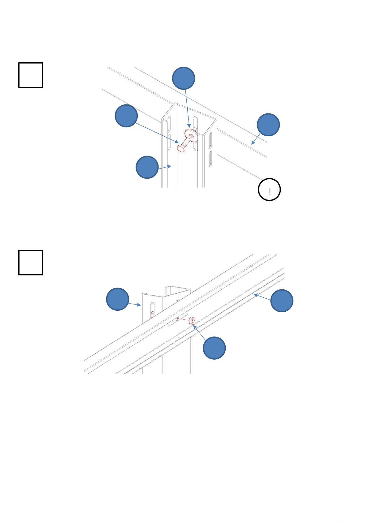
Step 3: Installation of rafter profiles
A
B
E
F
B
A
G
Torque:
100 Nm (A2/A4)
130 Nm (HV)
!

7
1
2
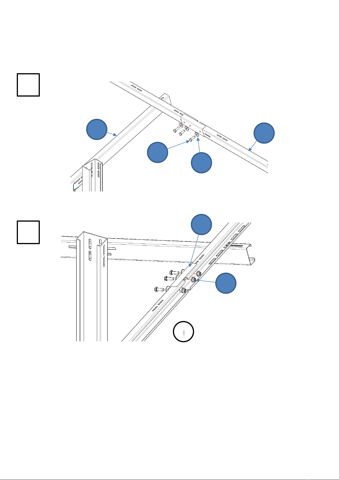
Step 4: Installation of diagonal braces
E
F
J
B
A
E
F
G
J
B
A
G
Torque:
100 Nm (A2/A4)
130 Nm (HV)
!

8
1
2
3
Step 5: Installation of purlins
G
B
E
F
C
G
B
C
Torque: 60 Nm
!
9
1
2
Step 6: Installation of purlin - connectors
The number of connectors to be used depends
on the table design.
Torque: 60 Nm
!
E
F
B
C
D
G
Questo manuale è adatto per i seguenti modelli
1
Indice


