OHTAKE OM-26M Manuale utente

NSIR MAE01
Read these instructions for the proper use of this machine.
After having read these instructions, keep them in a convenient place so you
or the operator can refer to them whenever necessary.
Operation Manual
QUICHER
NSRI Type
Automatic Screw Feeder
ὀព㸟㸸www.ohtake-root.co.jp ࡀᙜ♫၏୍ࡢ HP ࢻࣞࢫ࡛ࡍࠋ
ᘢ♫ࡢྡࢆ㦄ࡿഇࢧࢺࡈὀពୗࡉ࠸ࠋ⌧ᅾࠊᙜ♫ࡣ୰ᅜᅜෆᨭᗑࡣࡈࡊ࠸ࡲࡏࢇࠋ
ྛ栦ᐈ実ὀព㸸ࠕwww.ohtake-root.co.jp ᩎྖ၏୍ⓗᐁ᪉⨒❰㸪
┠๓㸪ᩎྖᅾ୰ᅜἐ᭷≆⢬ᡤ宻ⓗ୰ᅜᐁ⨒ࠋࠖ
ATTENTION : www.ohtake-root.co.jp is the only web site associated with our company.
We do not have any branches in China.
Operation Manual
・ Read these instructions for the proper use of this machine.
・ After having read these instructions, keep them in a convenient
place so you or the operator can refer to them whenever necessary.
自動ネジ供給機
OM-26M Type
Automatic Screw Feeder
OMM1MA02M
(Maintenance)

-1-
Contents
1. OVERVIEW OF THIS MACHINE -------------------- 1
2. BEFORE USE -------------------------------------------- 1
3. OPERATING PRECAUTIONS ----------------------- 2
4. NAMES OF MACHINE PARTS ---------------------- 5
5.
ADJUSTMENTS AND CHECKS BEFORE USE-------- 7
6. MAINTENANCE ----------------------------------------- 16
7.
PARTS ADJUSTMENTS AND REPLACEMENTS
----- 16
8. EXTERNAL OUTPUT SIGNALS------------------- 28
9. MISCELLANEOUS ----------------------------------- 30
10. TROUBLESHOOTING ------------------------------- 32
11. SPECIFICATIONS ------------------------------------- 38
12. EXTERNAL DIMENSIONS -------------------------- 40
13. WARRANTY -------------------------------------------- 41
2.BEFORE USE
Please check for the following accessories before operating the machine.
* Instruction Manual 1 copy * AC Adapter 1 unit
* Hexagonal Wrench 1 piece * Screwdriver 1 piece
* Ground Wire 1 piece
1.OVERVIEW OF THIS MACHINE
Thank you very much for selecting our Automatic Screw Feeder "OM-26M series ".
This machine can line up screws (Type M2 - M6) and supplies them one by one to help
the efciency of screw fastening work.
Different sizes of screws can be used by changing the rail and parts of the escaper assembly.
It can be used wherever there is a power source for an AC adapter.
Only steel screws may be used with this machine. Stainless steel or plastic screws cannot be used.

-2-
3.OPERATING PRECAUTIONS
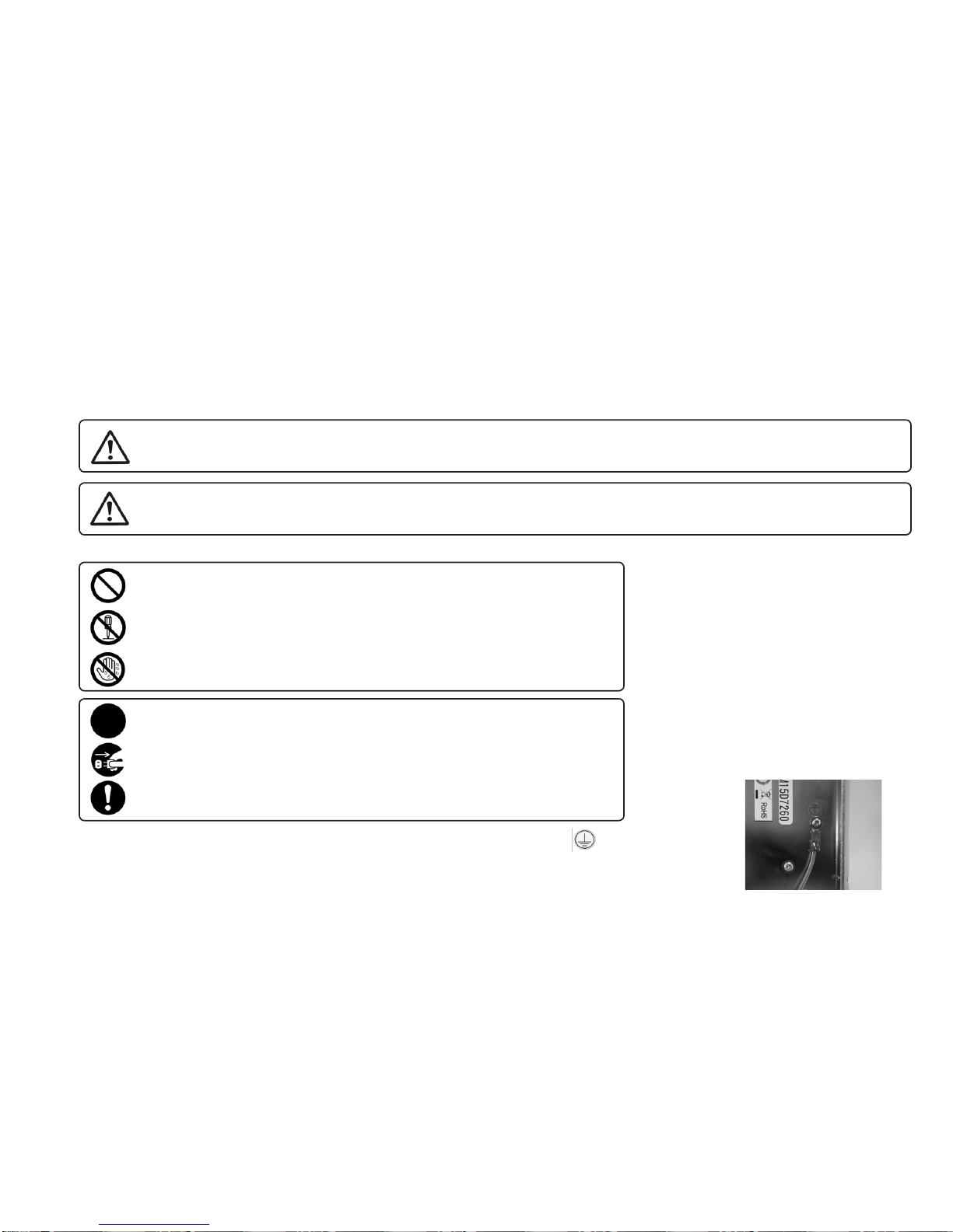
This manual contains safety alert symbols and signal words to help prevent injuries
to the user or damage to property.
◎Indications
This indicates there is a chance of death, serious injury or re if the instructions
are not followed.
This indicates there is a chance of personal injury or damage to property
if the instructions are not followed.
◎Symbols indicating type of danger and preventative measures
This indicates to stop operations.
Unplug power supply from wall outlet.
General caution.
Prohibited operation. Never do this!
Do not disassemble, modify or repair.
Do not touch with wet hands.
WARNING
CAUTION
When the earth wire is connected, loosen the screw near the mark once.
After attaching the earth wire,tighten the screw again.
the bottom of the main body

-3-
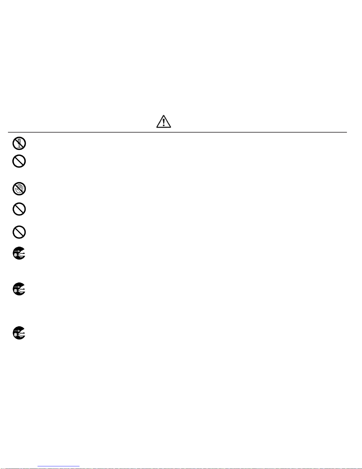
Do not disassemble the AC adapter as there is a risk of electric shock, re or malfunction.
Do not damage, alter or change the power cord. Do not place heavy objects on the cord.
Do not pull hard on the cord or twist the cord as it could be damaged, thereby causing a risk
of re or electric shock.
Do not handle the AC adapter with wet hands as it could cause an electric shock.
When using an outlet with AC100 ~240V, don't overload the electrical circuit.
Do not modify or remodel this machine as this may cause a re or electric shock.
Do not operate this machine near ammable liquids, gasses or materials as there could
be a risk of re or explosion.
Stop operating the machine and unplug the AC adapter from the wall outlet when you detect overheating,
smoke, a pungent odor or any other unusual condition, as there may be a risk of re or electric shock. Contact
the dealer, from which you purchased the machine, and have
it examined and repaired.
In the case of a thunderstorm, stop operating the machine, turn off the power and unplug
the AC adapter from the wall outlet. If there is lightning and thunder nearby, move away from the machine and
do not touch it or the AC adapter.
After the thunder stops, and when it is safe to do do so, check the machine. If there is any abnormality, contact
your dealer.
When performing maintenance, changing parts or when you sense an abnormality in the machine, turn the
power off and pull the AC adapter from the wall outlet.
WARNING

-4-
Do not bend, alter or damage the rail. Do not apply any oil. It is recommended that the user
clean the rail periodically.
Do not use any screw that is out of the specied range nor any screw that is oily or dirty.
When pick uping screws, do not exert excessive force or shock to the screws.
Do not allow any foreign material to enter the machine while in operation.
Do not put your ngers into the machine while in operation, otherwise an injury will result.
Use only the AC adpater supplied with this machine otherwise it may result in a re
or electric shock.
Do not install this machine in an unstable location otherwise it may fall causing damage or injury.
When moving the machine, always disconnect the AC adapter from the wall outlet or it may result in damage to
the cord, or cause a re or electric shock.
Turn off the machine and unplug the AC adapter from the wall outlet during closing hours
or if the machine will be unused for any extended period of time.
Do not operate this machine in overly humid or dusty conditions.
Keep the socket plug clean at all times otherwise it may cause a re or electric shock.
Do not operate the machine with tension on the AC adapter cord.
Keep the cord loose and untangled.
Always operate the machine with the upper cover in place, otherwise it may result in injury.
CAUTION

-5-
4.NAMES OF MACHINE PARTS
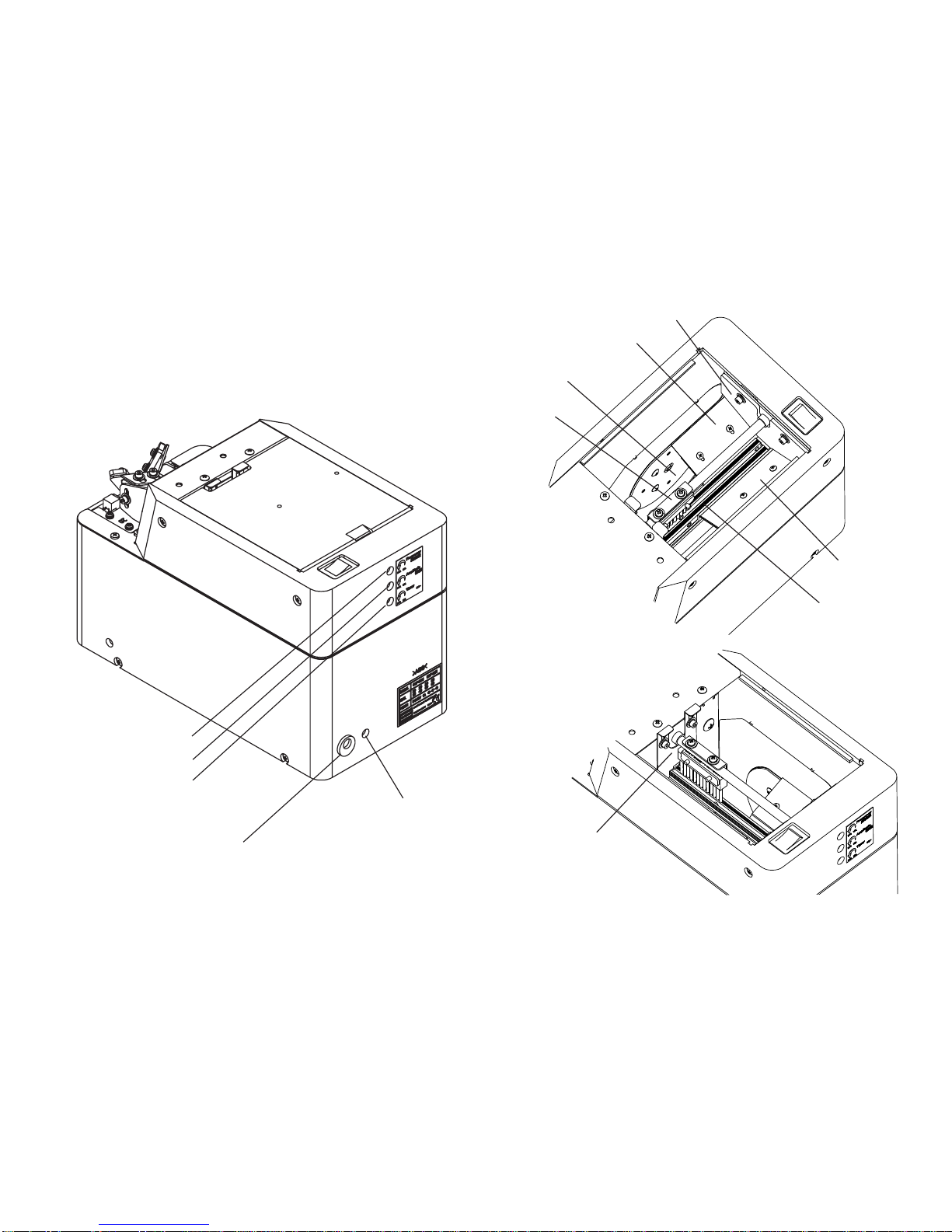
Top lid
Rail xing bolt
Power switch
Front cover
Front lower
cover
LED screw indicator
Sensor bracket
Escaper assembly xing bolts
(1 left / 1 right)
Holding plate
adjusting bolt
Holding plate
xing bolt Escaper guide-right
Holding plate
Light-emitting
sensor Light-receiving
sensor
Bit guide
Escaper
Stopper assembly Stopper
Bit guide bracket Bit guide bracket
attaching plate
Right guide
Left guide

-6-
1
1
2
2
3
3
4
4
5
5
6
6
A A
B B
C C
D D
名前 日付
TPO11061_OM2-26R(
2014/10/06
OIKAWA
A3
1 / 1
1
1
2
2
3
3
4
4
5
5
6
6
A A
B B
C C
D D
名前 日付
TPO11061_OM2-26R(
2014/10/06
OIKAWA
A3
1 / 1
Passing plate
Brush
Scraper-left
Scraper-right
Rail assembly
Rear cover
Scooping hopper
DC jack
Signal line out
Timer adjusting knob
Amplitude adjusting knob
Frequency adjusting knob
Right guide

-7-
5.
ADJUSTMENTS AND CHECKS BEFORE USE
5-1.
Checking the model number of the main body
Check if the machine has the parts which match the nominal diameter of
the screws to be loaded. Check the model number of the rail, escaper,
stopper assembly, escaper guide-right,
and passing plate by referring to the following table.
Before delivery, each section of the machine is checked and adjusted
with panhead screws matching the nominal diameters of the model
ordered. Operate the machine with the screws loaded to check that the
pick up is smooth. If the height or or shape of the screw head is different
or if the operation is regarded as abnormal, each section must be
readjusted.
If this is the case, make the following checks and adjustments:
Identication stamp
※This photo shows removal of the bit guide.
Stopper assembly Escaper Escaper guide-right
If the rail, escaper, stopper assembly, escaper guide-right and passing plate are replaced, screws with a different nominal
diameter can be accepted. After these parts are replaced, ne adjusting is required.
The respective adjusting procedures will be described elsewhere. Please read these procedures.
The rail identification
seal can be located
after removing the front
cover.
○ Check the screw load amount
○ Check and adjust the passing plate
○ Check and adjust the holding plate
○ Check and adjust the timer
○ Check and adjust the brush
○ Check and adjust the rail vibration
○ Check and adjust the front and rear sides of the rail
Passing plate
identication seal
㻾㼑㼒㼑㼞㼑㼚㼏㼑㻌㼠㼍㼎㼘㼑㻌㼛㼒㻌㼠㼔㼑㻌㼟㼜㼑㼏㼕㼒㼕㼑㼐㻌㼟㼏㼞㼑㼣㼟
㻿㼏㼞㼑㼣
㼒㼑㼑㼐㼑㼞
㼟㼑㼞㼕㼑㼟
㻿㼏㼞㼑㼣
㼒㼑㼑㼐㼑㼞
㼙㼛㼐㼑㼘
㻿㼏㼞㼑㼣
㼟㼕㼦㼑
㻱㼤㼏㼔㼍㼚㼓㼑㻌㼗㼕㼠
㻺㼛㻚
㻾㼍㼕㼘㻌㼙㼛㼐㼑㼘
㻺㼛㻚
㻱㼟㼏㼍㼜㼑㼞
㼙㼛㼐㼑㼘㻌㻺㼛㻚
㻿㼠㼛㼜㼜㼑㼞
㼍㼟㼟㼑㼙㼎㼘㼥
㼙㼛㼐㼑㼘㻌㻺㼛㻚
㻱㼟㼏㼍㼜㼑㼞
㻌㼓㼡㼕㼐㼑㻙㼞㼕㼓㼔㼠
㼙㼛㼐㼑㼘㻌㻺㼛㻚
㻼㼍㼟㼟㼕㼚㼓
㼜㼘㼍㼠㼑
㼙㼛㼐㼑㼘㻌㻺㼛㻚
㻿㼏㼞㼑㼣
㼟㼕㼦㼑
㻿㼏㼞㼑㼣㻌㼟㼔㼍㼒㼠
diameter(φ)
㻿㼏㼞㼑㼣
㼔㼑㼍㼐
㼐㼕㼍㼙㼑㼠㼑㼞
(φ)
㼃㼍㼟㼔㼑㼞
㼐㼕㼍㼙㼑㼠㼑㼞
(φ)
㻿㼏㼞㼑㼣
㼔㼑㼍㼐
㼠㼔㼕㼏㼗㼚㼑㼟㼟
(mm)
㻿㼏㼞㼑㼣
㼟㼔㼍㼒㼠
㼘㼑㼚㼓㼠㼔
(mm)
㻿㼑㼙㼟
㻰㼛㼡㼎㼘㼑
㼟㼑㼙㼟
㼃㼍㼟㼔㼑㼞
㼔㼑㼍㼐
㻻㻹㻙㻞㻢㻹㻞㻜 φ㻞㻚㻜 㻻㻹㻹㻞㻜㻿㻱㼀 㻻㻹㻹㻞㻜 㻿㻵㻱㻞㻜 㻿㻵㻱㻿㻞㻜 㻿㻵㻱㻹㻞㻜 φ㻞㻚㻜 1.9~2.1 2.4~6 2.4~10 0.35~6 2.6~25 ○ ○ ○ ○ ○ ○
㻻㻹㻙㻞㻢㻹㻞㻟 φ㻞㻚㻟 㻻㻹㻹㻞㻟㻿㻱㼀 㻻㻹㻹㻞㻟 㻿㻵㻱㻞㻟 㻿㻵㻱㻿㻞㻟 㻿㻵㻱㻹㻞㻟 φ㻞㻚㻟 2.2~2.4 2.7~6 2.7~10 0.35~6 2.9~25 ○ ○ ○ ○ ○ ○
㻻㻹㻙㻞㻢㻹㻞㻢 φ㻞㻚㻢 㻻㻹㻹㻞㻢㻿㻱㼀 㻻㻹㻹㻞㻢 㻿㻵㻱㻞㻢 㻿㻵㻱㻿㻞㻢 㻿㻵㻱㻹㻞㻢 φ㻞㻚㻢 2.5~2.7 3.0~6 3.0~10 0.35~6 3.2~25 ○ ○ ○ ○ ○ ○
㻻㻹㻙㻞㻢㻹㻟㻜 φ㻟㻚㻜 㻻㻹㻹㻟㻜㻿㻱㼀 㻻㻹㻹㻟㻜 㻿㻵㻱㻟㻜 㻿㻵㻱㻿㻟㻜 㻿㻵㻱㻹㻟㻜 φ㻟㻚㻜 2.9~3.2 3.5~6 3.5~11 0.35~6 3.6~25 ○ ○ ○ ○ ○ ○
㻻㻹㻙㻞㻢㻹㻟㻡 φ㻟㻚㻡 㻻㻹㻹㻟㻡㻿㻱㼀 㻻㻹㻹㻟㻡 㻿㻵㻱㻟㻡 㻿㻵㻱㻿㻟㻡 㻿㻵㻱㻹㻟㻡 φ㻟㻚㻡 3.4~3.7 4.0~8 4.0~11 0.35~6.5 4.1~25 ○ ○ ○ ○ ○ ○
㻻㻹㻙㻞㻢㻹㻠㻜 φ㻠㻚㻜 㻻㻹㻹㻠㻜㻿㻱㼀 㻻㻹㻹㻠㻜 㻿㻵㻱㻠㻜 㻿㻵㻱㻿㻠㻜 㻿㻵㻱㻹㻠㻜 φ㻠㻚㻜 3.8~4.2 4.5~8 4.5~12 0.35~6.5 4.6~25 ○ ○ ○ ○ ○ ○
㻻㻹㻙㻞㻢㻹㻡㻜 φ㻡㻚㻜 㻻㻹㻹㻡㻜㻿㻱㼀 㻻㻹㻹㻡㻜 㻿㻵㻱㻡㻜 㻿㻵㻱㻿㻡㻜 㻿㻵㻱㻹㻡㻜 㻻㻹㻡㻜 φ㻡㻚㻜 4.8~5.2 5.5~10 5.5~12 0.35~7 5.6~25 ○ ○ ○ ○ ○ ○
㻻㻹㻙㻞㻢㻹㻢㻜 φ㻢㻚㻜 㻻㻹㻹㻢㻜㻿㻱㼀 㻻㻹㻹㻢㻜 㻿㻵㻱㻢㻜 㻿㻵㻱㻿㻢㻜 㻿㻵㻱㻹㻢㻜 㻻㻹㻢㻜 φ㻢㻚㻜 5.8~6.2 6.5~11 6.5~12 0.35~7.5 6.6~25 ○ ○ ○ ○ ○ ○
㻌㻌㻌㻌㻌
㻌
㻻㻹㻙㻞㻢㻹
㻻㻹㻞㻜㻙㻟㻜
㻻㻹㻟㻡㻙㻠㻜
㻿㼔㼍㼜㼑㻌㼛㼒㻌㼟㼏㼞㼑㼣㻌㼔㼑㼍㼐
㻼㼍㼚㻌㼔㼑㼍㼐
㼎㼕㼚㼐
㻲㼘㼍㼠㻌㼔㼑㼍㼐
㼔㼑㼤㼍㼓㼛㼚
㼒㼘㼍㼚㼓㼑
㼎㼛㼘㼠

-8-
5-2.Basic operations
○Loading the screws
・Turn the power switch ON and OFF so that the brush stops vertically above
the rail.
・Open the top cover and load screws on the left and right side of the rail
evenly.
・Do not load screws above the surface of the rail.
・Be sure to determine the screw load by observing the machine while it is in
operation.
Screws with a diameter larger than 5 or longer than 20mm,
under the head, should not be loaded higher than the rail bottom.
○Turning ON the power
・Use only the adapter supplied with this machine to connect it to a wall outlet.
When you turn the power on, the switch lamp lights up, the motor rotates and
screws are scooped onto the rail.
・The rail vibrates to deliver screws towards the end of the rail, then the
escaper rotates to deliver screws to the pick up spot. When the screws come
to the stopper, the LED indicator lights up and the escaper stops rotating.
Rail cover
(INDICATION:The maximum screw load must not be
over 30mm below the rail-groove surface.)
Disassembled state
Do not load screws
above this point.
(Rail Bottom)
Rail cover
[CAUTION]
・The type and length of screw changes the load capacity so check and adjust
the load accordingly.
・Do not overload the hopper with screws otherwise it may cause a
malfunction or damage the machine.
・This machine accepts only steel screws. Plastic or stainless screws are not
accepted.
[CAUTION] Use only the AC adapter supplied with this machine
otherwise it may cause damage to the machine.

-9-
○Pick uping Screws
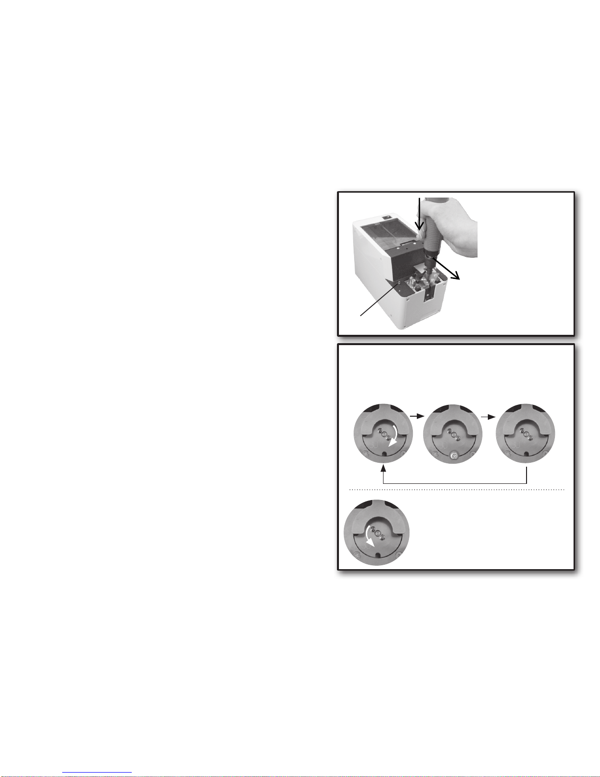
・Pick up the screws at the stopper with the electric screw driver.
Use the bit guide to put the screwdriver down vertically into the screwhead's slots,
then pull the screwdriver, horizontally, towards you as pick uping the screw.
・When inserting the screwdriver into the screwhead slots, do not use excessive force
as it may alter the position of the escaper or cause damage to the machine.
・To insert the screwdriver bit into the screwhead slots properly, it may be necessary to
twist the driver slightly.
・Use a driver bit which corresponds with the screw's diameter.
○Action of the escaper
・The escaper rotates 90° clockwise--> stops for about 0.6 seconds
--> and rotates again 90° clockwise.
When a screw is caught in the escaper and the notch position is altered, the escaper
automatically rotates to the left, as a reference point run, in order to adjust the notch
position and then returns to the right rotation.
・This machine continues its operation when no screw is found at the screw pick up
spot. The machine continues operating with a screw at the pick up spot but will stop,
after a certain lapse of time, if the screw is not picked up. After the screw is picked
up, the machine starts operating again. This time lapse can be varied by adjusting
the timer.
・When no screw is found at the pick up site after a certain lapse of time, the rail
vibration increases.
(The vibration sound, also, increases however, this is not a problem.)
If no screw is still not found at the pick up site, then the machine stops operating. At
this time the escaper keeps rotating. When you want to start operation again, turn
the power switch OFF and ON again.
LED screw indicator
①
②
①Put the screwdriver
down vertically as
twisting it slightly and
insert the bit into the
screwhead slots properly.
②Pull the screwdriver
towards you, horizontallly
and pick up the screw.
Accepting a screw.
LED screw indicator
is OFF
The screw is carried to
the pick up site.
LED screw indicator is
ON
Pick uping the screw
at the pick up site.
LED screw indicator is
OFF
The rotation of the escaper, in the opposite
direction, is a reference point run of the escaper
motor.
The rotation of the escaper, in the opposite
direction, occurs when the power is turned on and
the starting point of the escaper is not alligned
with the reference point of the escaper motor.
During regular operation, as in the gure above,
the escaper rotates clockwise.
(Reference)
○Action of the escaper
Indice