Olivetti EXPLOR@460 Manuale utente

User’s Manual
EXPLOR@460

EXPLOR@460
Copyrights
©2016 All rights reserved. The information in this document is subject to change without prior notice in
order to improve reliability, design and function and does not represent a commitment on the part of the
manufacturer.
This document contains proprietary information protected by copyright. All rights are reserved. No
part of this manual may be reproduced by any mechanical, electronic, or other means in any form
without prior written permission of the manufacturer.
All trademarks are property of their respective owners
Liability Disclaimer
In no event will the manufacturer be liable for direct, indirect, special, incidental, or consequential
damages arising out of the use or inability to use the product or documentation, even if advised of the
possibility of such damages.
Regulatory Information
CE Notice
This device complies with EMC directives 2004/108/EC and 2014/30/EU issued by the
Commission of the European Community.

EXPLOR@460
Contents
iii
Contents
Copyrights.............................................................................................. ii
Liability Disclaimer ................................................................................ ii
Regulatory Information.......................................................................... ii
CE Notice .............................................................................................................ii
Contents ................................................................................................ iii
1. Hardware Setup.................................................................................. 4
1.1. Packing Contents .........................................................................................4
1.2. Quick Tour.....................................................................................................5
Front View......................................................................................................5
Back View.......................................................................................................5
Back Panel I/O...............................................................................................6
1.3. Basic Peripherals Installation......................................................................7
Power Adapter................................................................................................7
USB Mouse, USB Keyboard and USB ODD..................................................8
LAN Cable......................................................................................................8
Cash Drawer ..................................................................................................9
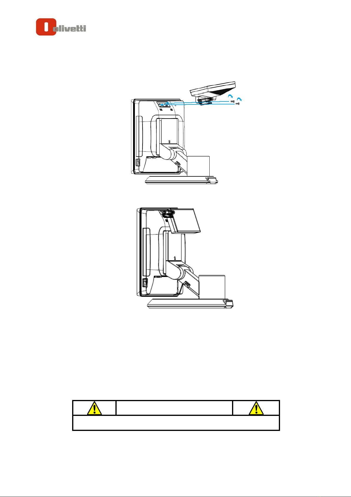
Customer Display...........................................................................................9
2nd Display ..................................................................................................12
MSR.............................................................................................................16
1.4. Adjust Angle................................................................................................18
1.5. Turn on the device......................................................................................19
2. I/O Definition..................................................................................... 20
2.1. Power Connector........................................................................................20
2.2. Serial Port ...................................................................................................21
2.3. VGA Port......................................................................................................22
2.4. COM 1.2 (10-Pin RJ50) ...............................................................................23
2.5. Cash Drawer ...............................................................................................24
3. Specification..................................................................................... 27

EXPLOR@460
Chapter 1
4
1.
1. Hardware Setup
1.1. Packing Contents
1. EXPLOR@460X 1
5. Recovery DVD x 1
2. Power Adapter X 1
6. Safety and Disposal Information
for Series X 1
3. EU Power Cord X 1
7. Drive and Utility DVD X 1
4. RJ50 to DB9 COM port adapter cable X 1
8. Cable Cover X 1

EXPLOR@460
Chapter 1
5
1.2. Quick Tour
Front View
LED Indicator
A.
The Power indicator will glow green when power is on.
Back View
A.
Customer Display mounting
hole cover
D. Power switch
B. Hinge Cover E. I/O cover
C. MSR cover
A
A
B
C
D
E

EXPLOR@460
Chapter 1
6
Back Panel I/O
A.
19VDC in
G.
LAN
B.
12VDC out
H.
USB 3.0
C.
CD/DIO (for cash drawer)
I.
Mini Display Port
D.
COM1
J.
COM3
E.
COM2
K.
VGA
F. USB2.0 x 4
CAUTION
* Note: Please use 10-pin RJ50 connector, 8-pin RJ45 is incompatible.

EXPLOR@460
Chapter 1
7
1.3. Basic Peripherals Installation
All cables and wires from peripherals to the POS device are recommended to
connected as the direction as shown below.
Power Adapter
Important!
Plug theAC adapter into the POS/PPC, and then connect to the mains power
supply.
Connect the 4-pin output jack of the adapter to the DC 19V jack on the back panel
of the device.

EXPLOR@460
Chapter 1
8
USB Mouse, USB Keyboard and USB ODD
Connect your USB Mouse, USB Keyboard and USB ODD to USB ports on the
back panel of the device.
LAN Cable
Connect one end of RJ-45 LAN cable to the LAN port on the back panel of the
device, another end to your internet device.

EXPLOR@460
Chapter 1
9
Cash Drawer
Connect one end of RJ-12 cable to the Cash Drawer port on the back panel of the
device, another end to your cash drawer.
Customer Display
1. Remover the customer display mounting hole cover from the device and pull
out the connector from the device.
2. Adjust the hinge of the customer display, and then connect to the device as
shown below.

EXPLOR@460
Chapter 1
10
3. Mount the customer display to the device and tighten the two PHILLIPS M3
screws as shown below.
4. Finished.
B. Power Supply Configuration
Power up the device and hit the DEL key to enter the BIOS. When the BIOS screen
appears use the TAB key to select Advanced. Use the arrow keys to select Super IO
Configuration then type ENTER. The screen below will appear. Use the arrow keys to
select Serial Port 6 RI/12V depending on what port the customer display is connected
to. Select 12V to enable power to the correct COM port. Type F10 to save the settings
and exit the BIOS setup.
WARNING
Never enable the 12V power without the customer display attached and
be sure to disable the 12V power before removing the customer display.
Indice
Manuali Terminale di pagamento popolari di altre marche

Ingenico
Ingenico iWL250B Manuale utente

Optimum
Optimum M4230 Manuale utente

Triton
Triton RL5000 Manuale utente

Ingenico group
Ingenico group Lane/8000 Manuale utente

Gilbarco
Gilbarco FlexPay IV CRIND Manuale di installazione e funzionamento

Infinite Peripherals
Infinite Peripherals Infinea Tab Lite Manuale utente


