
Omega Vehicle Security freedom OM-550 Manuale utente

OM-550 uiu
Table of Contents
Introduction..........................................................................................................................................iii
•Terms used in this Manual...........................................................................................................iii
•Product Symbols.......................................................................................................................... iii
Operator Safety Information ................................................................................................................iv
1.0 UNPACKING.....................................................................................................................................1
2.0 FEATURES.......................................................................................................................................2
2.1 OM-550 FEATURES..................................................................................................................2
2.1.1 ACTIVITY LED & HORN...................................................................................................3
2.1.2 KEYPAD............................................................................................................................4
•ON-OFF........................................................................................................................5
•RUN ..............................................................................................................................6
•STOP.............................................................................................................................7
•PROG/EXIT...................................................................................................................7
•OK.................................................................................................................................7
2.1.3 CHANNEL CONNECTORS..............................................................................................8
2.1.4 PRINTER WINDOW.........................................................................................................9
2.1.5 THERMAL PAPER..........................................................................................................10
2.1.6 BATTERY COVER..........................................................................................................10
2.1.7 DC JACK.........................................................................................................................10
2.1.8 SERIAL DATA PORT......................................................................................................10
2.1.9 GAIN ADJUST................................................................................................................11
2.1.10 TILT STAND..................................................................................................................11
2.2 POWER SUPPLIES.................................................................................................................12
2.3 INPUTS....................................................................................................................................13
2.3.1 VOLTAGE (TRANSDUCER) INPUTS............................................................................13
2.3.2 PROBES.........................................................................................................................13
2.3.3 THERMOCOUPLE INPUTS...........................................................................................14
2.4 PROGRAMMED FEATURES..................................................................................................15
2.4.1 DATA CACHE.................................................................................................................15
2.4.2 STATISTICS ...................................................................................................................16
2.4.3 POWER-SAVE MODE ...................................................................................................17
2.4.4 LOW BATTERY OPERATION........................................................................................17
2.4.5 BATTERY CHECK..........................................................................................................17

OM-550 uiiu
3.0 SET-UP...........................................................................................................................................18
3.1 POWER CONNECTION..........................................................................................................18
3.1.1 BATTERY INSTALLATION.............................................................................................18
3.1.2 CONNECTING THE AC POWER ADAPTER................................................................19
3.1.3 CONNECTING THE DC POWER CABLE.....................................................................19
3.2 PAPER INSTALLATION ..........................................................................................................20
3.3 DATA PORT CONNECTION...................................................................................................21
4.0 PROGRAMMING.............................................................................................................................22
4.1 PROGRAMMING KEYS ..........................................................................................................23
4.2 PRINT FORMATTING..............................................................................................................24
4.3 TEMPERATURE CHANNELS.................................................................................................25
4.4 VOLTAGE CHANNELS............................................................................................................25
4.5 MATH PSEUDO-CHANNEL....................................................................................................26
4.6 LOG INTERVAL.......................................................................................................................27
4.7 OPERATION AT FULL CACHE (RECORDING TIME)...........................................................28
4.8 DATE........................................................................................................................................29
4.9 TIME.........................................................................................................................................29
4.10 TEMPERATURE UNITS........................................................................................................29
4.11 REJECTION FREQUENCY...................................................................................................29
4.12 CALIBRATION MODE...........................................................................................................30
4.13 TADJUST...............................................................................................................................31
4.14 VOLTAGE INPUT SCALING..................................................................................................32
4.14.1 MATCHING TRANSDUCERS TO THE OM-550..........................................................32
4.14.2 MATCHING A VOLTAGE TRANSDUCER...................................................................32
4.14.3 MATCHING A CURRENT TRANSDUCER..................................................................33
4.14.4 DATA SCALING (mX + b calculation)..........................................................................34
4.14.5 MATCHING AND SCALING A VOLTAGE TRANSDUCER.........................................35
4.14.6 MATCHING AND SCALING A CURRENT TRANSDUCER........................................37
4.15 UNIT LABELS ........................................................................................................................39
5.0 OPERATION...................................................................................................................................40
APPENDIX A: CALIBRATION ..............................................................................................................45
•MANUAL RESET........................................................................................................................45
•PERFORMING A MANUAL RESET.....................................................................................45
•CALIBRATION PROCEDURE....................................................................................................46
•VOLTAGE ADJUSTMENT PROCEDURE: ..........................................................................47
•THERMOCOUPLE ADJUSTMENT PROCEDURE:.............................................................47
•EXITING CAL MODE............................................................................................................48
APPENDIX B: SPECIFICATIONS.........................................................................................................49
OM-550 uiiiu
Introduction
This User’s Guide explains how to use OM-550.
This manual is written for users of varied experience. If a section covers information
you already know, feel free to skip to the next section.
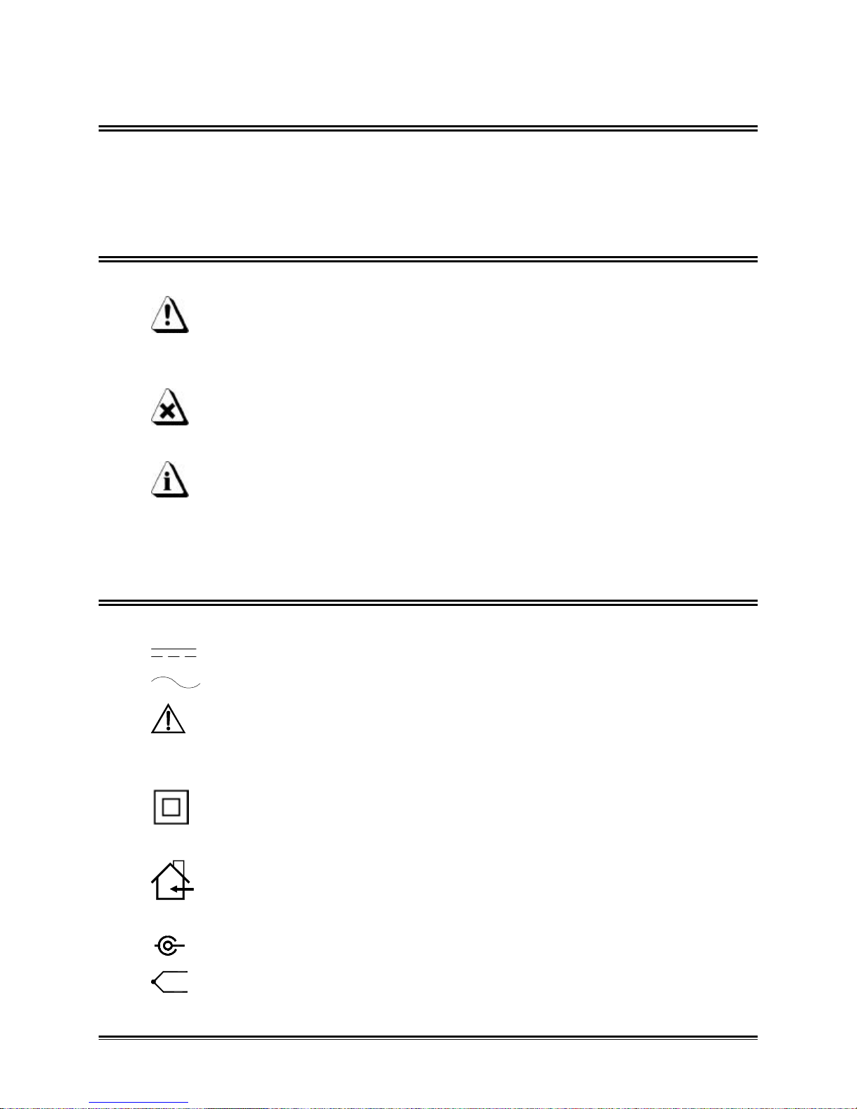
•• Terms used in this Manual
In this manual, the following definitions are used for special terms and symbols.
•Informs the user that the note identifies conditions or practices that
could result in personal injury or damage to property other than the
equipment.
•Informs the user that the note identifies conditions or practices that
could result in damage to the equipment.
•Informs the user that the note includes important information.
•Thermocouple may be referred to as T/C.
•The OM-550 Datalogger may be referred to as “Logger”.
•• Product Symbols
The following symbols may be present on the Product:
•Direct Current (DC) Power
•Alternating Current (AC) Power
•CAUTION: Whenever this internationally recognized symbol is used
on the product, additional information concerning that particular
feature or function appears in the manual.
•Battery Charger protected throughout by double or reinforced
insulation.
•Indoor use only. For electric-shock protection, always operate the
battery charger in a protected, indoor location.
•Input power connector
•Thermocouple connection

OM-550 uivu
Operator Safety Information
The safety information in this summary is for the benefit of operating personnel.
Warnings and Cautions will also be found throughout the manual where they apply.
PRODUCT USAGE WARNINGS:
For fire and electric shock protection, DO NOT connect the input channels to objects at
elevated electrical potential. The common terminal of each measurement input channel
is not isolated from the common terminal of the 9V DC input power connector and the
RS-232 serial data port while that channel is being measured.
This interconnected common circuitry is not connected to ground or to the
enclosure of the OM-550. If the OM-550 is interconnected to a desktop computer,
its internal circuitry very likely could be connected to ground through the serial
data port of the computer. The enclosure and the measurement circuitry provide
functional isolation of the measurement and data circuitry sufficient to allow for
small electrical noise-related potentials to occur. This functional isolation is not
intended for electrical safety isolation. Therefore for electric-shock protection
and to prevent fire and damage to data interconnect wiring due to high currents,
the input channels must not be connected to objects at elevated electrical
potential.
•Do not operate the OM-550 in flammable or explosive atmospheres. Such usage
constitutes a fire or explosion risk.
•For electric-shock protection, only operate the AC power adapter indoor
location.
•For continued fire and electric shock protection, use only the specified power
adapter.
•For continued fire protection, use only the specified optional DC power cable,
which incorporates a two-ampere fuse.
A two-ampere fuse is incorporated in the cigarette lighter plug which is part of
the DC power cable. This fuse provides overcurrent protection should a short or
overload circuit occur in the OM-550 or the DC power cable.

OM-550 uvu
For protection of the OM-550 itself, observe the following:
•Do not immerse the OM-550 in liquids.
•Do not subject the OM-550 to sharp impacts or drops.
•Do not expose the OM-550 to corrosive environments.
•Extended exposure to temperatures below the specified minimum may
damage the battery (optional external rechargeable battery pack only).
•Extended exposure to temperatures above the specified maximum may
damage the OM-550 itself or its optional external rechargeable battery
pack.
•Do not excessively stress the power input, the RS-232 serial data, and the
accessory port connections.
The warranty will not cover damage caused by neglect or abuse of this product.
To maintain the safety features incorporated in this product, operation must be in
strict compliance with the requirements specified herein.
OM-550 u1u
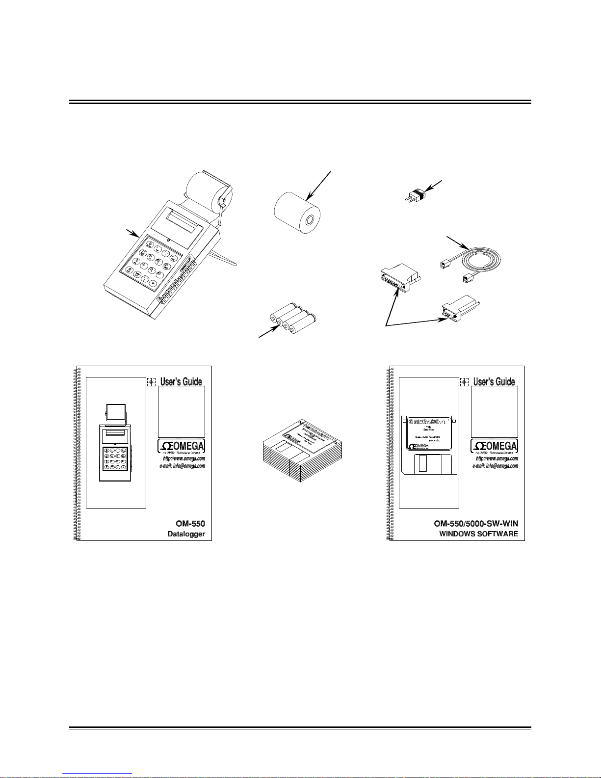
1.0 UNPACKING
Unpack the unit carefully. Be sure to check for options and accessories that may have
been packed separately. Retain the shipping carton for reshipment (for recalibration or
any other purpose).
Figure 1-1
OM-550
VOLTAGE INPUT
CONNECTOR
RS-232
CABLE
CABLE
ADAPTERS
(4) 1.5V AA
BATTERIES
OM-550/5000
WINDOWS SOFTWARE
OM-550 HARDWARE
USERS GUIDE OM-550/5000 WINDOWS
SOFTWARE USERS GUIDE
THERMAL
PAPER ROLL
OM-550 u2u
2.0 FEATURES
This section explains the Features for the OM-550 System and optional items.
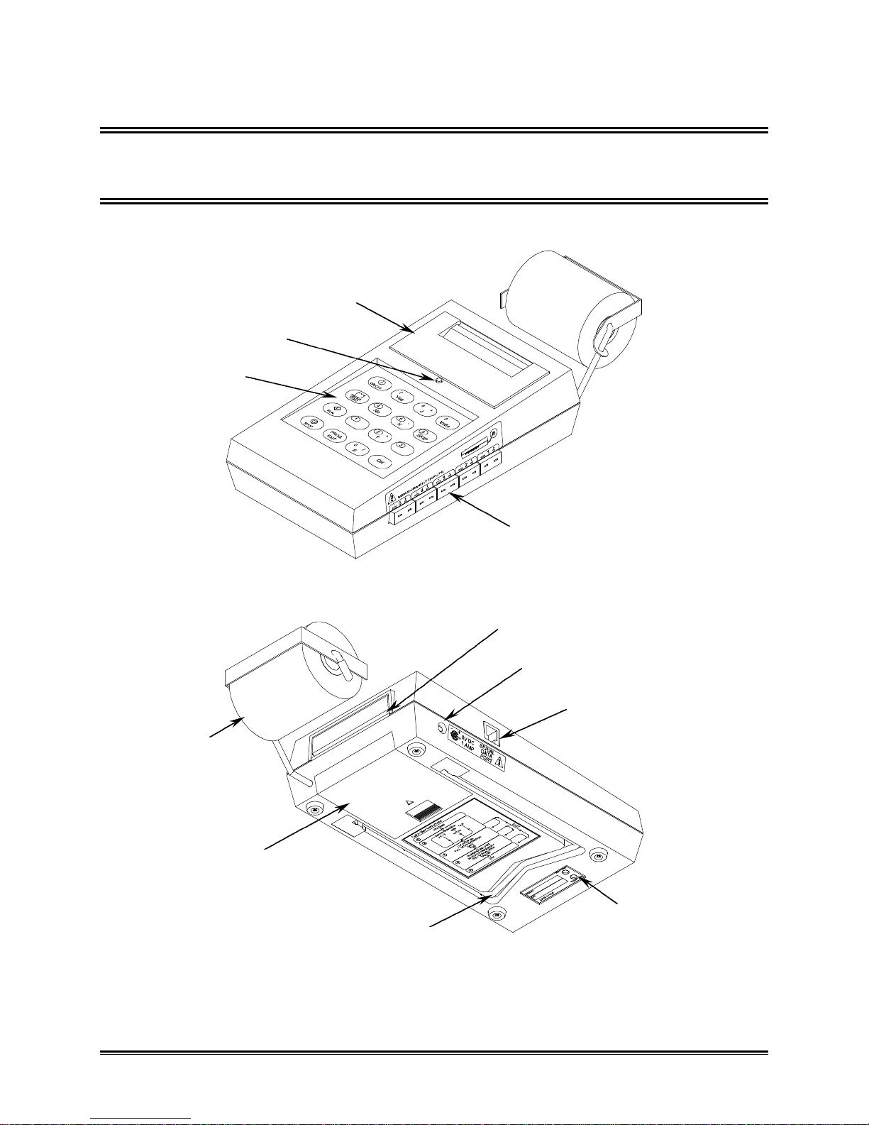
2.1 OM-550 FEATURES
OM-550 features:
Figure 2-1
Figure 2-2
CHANNEL
CONNECTORS
KEYPAD
PRINTER WINDOW
ACTIVITY LED
THERMAL
PAPER
TILT STAND
BATTERY
COVER
GAIN ADJUST
SERIAL DATA PORT
9V DC RECEPTICAL
THERMAL PAPER FEED
OM-550 u3u
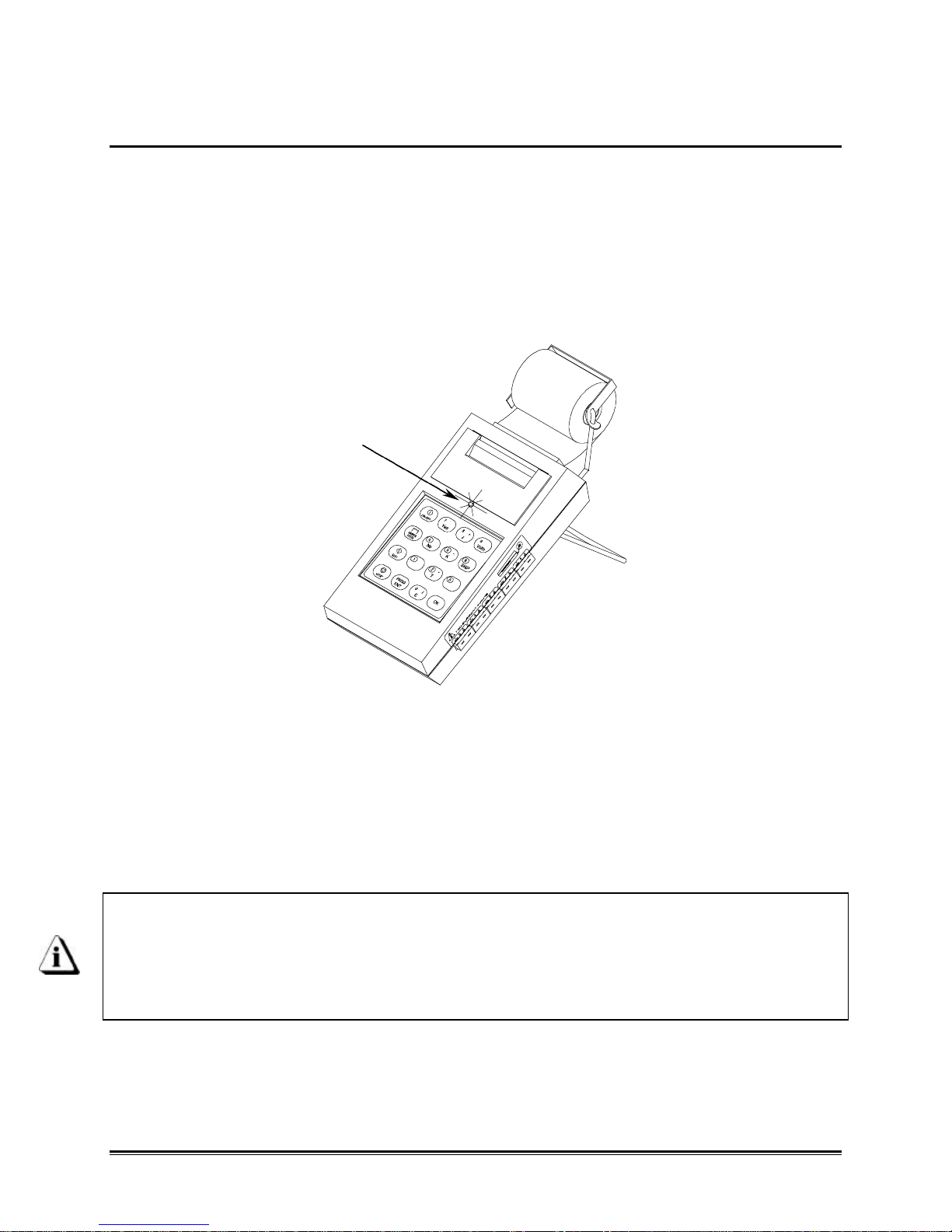
2.1.1 ACTIVITY LED & HORN
The Activity LED and internal horn provide a quick indication of the unit's status. For
example a short, periodic beep and flash indicates that the OM-550 is “ON” but not
being programmed.
The horn produces two different sounds, a beep and blat. Valid key closures produce
the beep sound and invalid keys produce the blat. For example, the OK key is only
used in programming. Pressing the OK key when not programming will produce a blat
sound.
Figure 2-3
•A periodic beep-beep and flash-flash indicates that the OM-550 is being
programmed.
•Key closures override this regular activity with a steady beep (or blat) whenever
a key is pressed.
•If no activity is evident (beeps and flashes, or printing), the unit is “OFF”.
Menus are printed when a choice is available. Then, when the operator presses a
key the resulting Selection is printed to confirm the action. In most cases, the
user need not wait for a menu to print before making a selection. Experienced
operators can operate the unit very swiftly, with little printing. If the unit blats,
just wait for the menu to print, then continue by pressing the correct key(s).
ACTIVITY LED
OM-550 u4u
2.1.2 KEYPAD
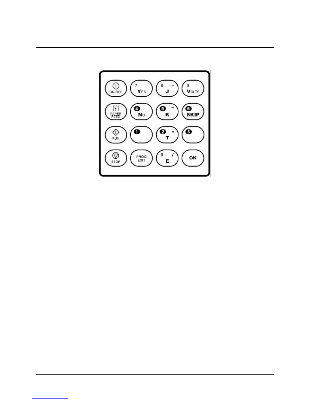
The Keypad has more than one function and many are self-evident, so only the main
key functions are discussed here.
Figure 2-4
The ON-OFF and PROG/EXIT keys are toggles. They are often discussed here by
separate function to avoid confusion.
For example, the ON key and the OFF key are the same key but its function changes
(toggles) between “ON” and “OFF”. All keys but the ON key are disabled when the unit
is “OFF”.
OM-550 u5u
•• ON-OFF
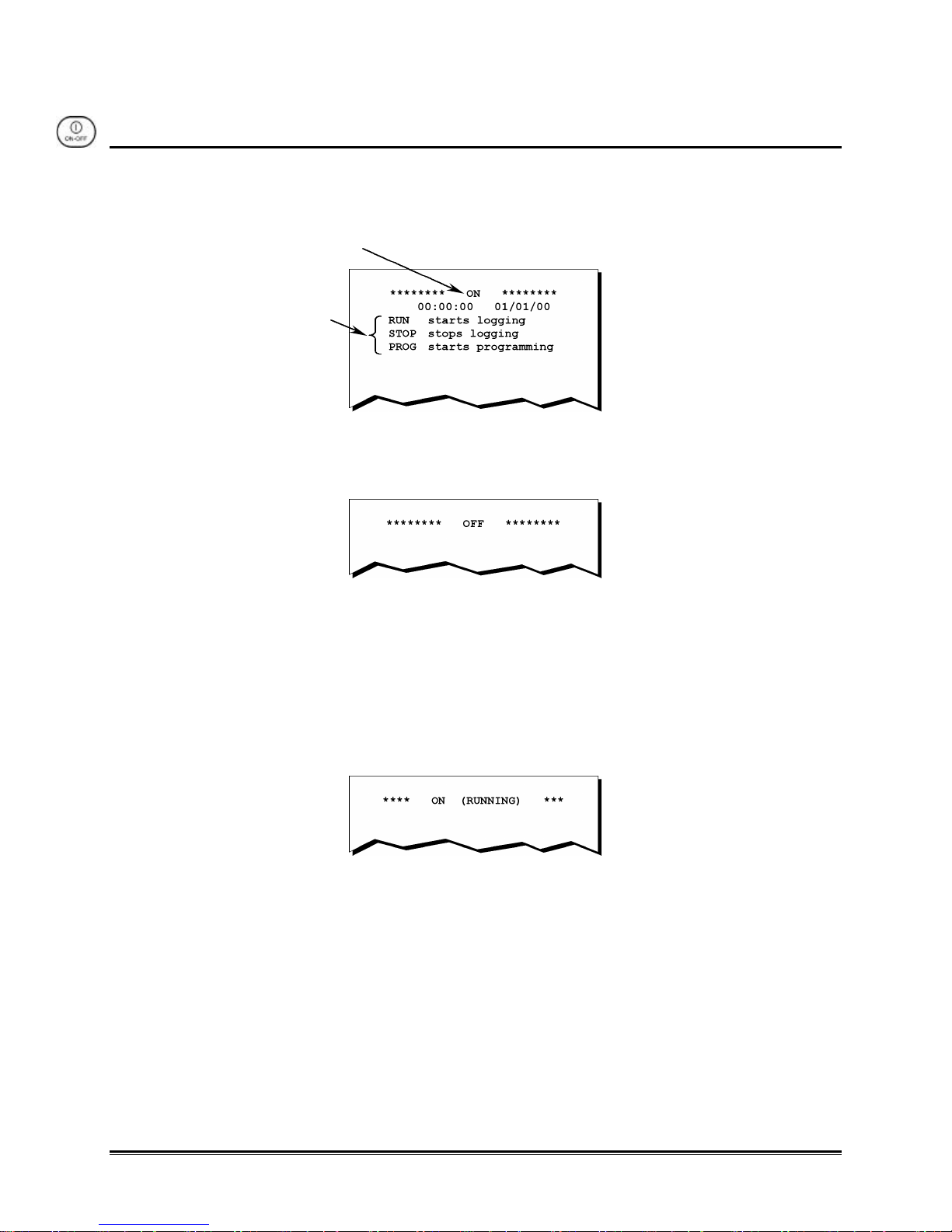
The ON-OFF key activates the OM-550. If the unit is “OFF”, pressing the ON key will
activate it, light the Activity LED and beep the horn. When the key is released, the unit
will print the key name, time, date, and a command menu:
Figure 2-5
If the OM-550 is “ON”, pressing the OFF key will cause it to print:
Figure 2-6
... then deactivate. It will remain “OFF” until the ON key is pressed.
The OM-550 can turn itself “OFF” (power save mode) when logging at long intervals, to
conserve power (refer to section 2.4.3 POWER-SAVE MODE for more information). If
the unit is powered down, pressing the ON key will activate the unit but only the key
name will print, with the following message:
Figure 2-7
KEY NAME
MENU
Indice


