omnikine JV series Manuale utente

03
Car & Home Security System /
Please make sure of usage after bearing the following
contents in mind to shorten the safety, and product
failure before its operation.
1. Do not shock in move, and installation.
2. Please check rating voltage (mini type : DC12V 3.0A / mobile type : DC12V)
before power on.
3. Please check power off before installation.
4. Avoid any place with moisture because of electric shock, and fire.
5. Avoid any place with moisture, dust, or soot.
6. Avoid any place with direct sunlight, or heating appliances.
7. Avoid high, or low temperature.
8. Procure sufficient air ventilation for the connection of system wiring.
9. Don't install near to electronic devices such as radio, or TV.
10. Install in sufficient air ventilation, and no vibration.
11. Please take care of not putting the electric product into the cooling fan.
12. Don't use water, or cleanser in surface cleaning to prevent an electric shock.
13. Please clean system by dry towel in external cleaning.
14. Do not pull power cord forcefully.
15. Do not place any heavy object on the main system.
16.
Do not open, or disassemble DVR without an assistance of qualified service personnel.
17. Please power off in case of moving DVR.
18. Please equip with the safety facility to diminish the loss for electricity failure,
and lightning.
19.
Do not connect signal cable of camera with DVR system during camera installation.
20. Please power off immediately, and contact manufacturer, or supplier if you
catch strange scent, or smog.
NOTICE FOR SAFETY

/Car & Home Security System
04
NOTICE FOR SAFETY
- This equipment had been tested and found to comply with the limits for
CLASS A digital deice, pursuant to Part 15 of FCC Rules.
- These limits are designed to provide reasonable protection against
harmful interface when the equipment is operated in a commercial
environment.
1. Quick Setup Guide
2. Specification
3. Operation
4. Backup Viewer
5. Menu Setup
6. Troubleshooting
7. Warranty
FCC Compliance Statement Caution :
Any change, or modification in construction of this device which are
not expressly approved the party responsible for compliance could
avoid the user s authority to operate the equipment .
NOTE :
This equipment has been tested, and found to comply with the limits
for a Class A digital device, pursuant to part 15 of the FCC rules. This
limits are designed to provide reasonable protection against harmful
interference when the equipment is operated in a commercial
environment. This equipment generates, uses, can radiate radio
frequency energy, and , if not installed, and used in accordance with
the instruction manual, may cause harmful interference to radio
communications. Operation of this equipment in a residential area is
likely to cause harmful interference in which cause the user will be
required to convert the interference at his own expense.
Contents

Quick Setup Guide
Car & Home Security System
Quick Setup Guide
STEP 1 Package Details
STEP 2 HDD Installation
STEP 3 Camera & Monitor Connection
STEP 4 Menu Setup
STEP 5 Operation Check
1. Monitor Check
2. LED Check
STEP 6 Backup Viewer
1. Date & Time Setup
2. Record Setup

/Car & Home Security System
08 09
Car & Home Security System /
Quick Setup Guide Quick Setup Guide
A Type (MINI)
STEP1.1 Package Details
DVR
Remote controller
Power cord
Battery
CD
A/V out cable
Adaptor
Manual
B Type (Mobile)
DVR
Remote controller
Screw
Screw
Battery
CD
A/V out cable
Bracket
Manual
Cigar jack
STEP 1.2 Optional Accessories
2. Camera input cable
1. Camera extention cable
1) Type A (MINI) : 60 feet cable
2) Type B (Mobile) : 20 feet cable
- DVR can support camera power up to max. 250 mA. If camera power is
over 250 mA, its own adaptor must be required.
-
Otherwise, DVR may be damaged and work abnormally.
For installation, please contact technial service personnel.
- Input : DC12V - DC35V - Output : DC 12V - Advanced power management
3. DC to DC converter (for car)
- Wired reomte control - LED indicator
4. External wired controller

/Car & Home Security System
10 11
Car & Home Security System /
Quick Setup Guide Quick Setup Guide
STEP2 HDD Installation
1. Unscrew 4 fixed screws on
the bottom of case.
2. Disassemble rear panel and
take out main board.
3. Fix HDD to SATA connector on
main board.
4. Insert rubber rings into screws
and then screw them to fix HDD
& main baord to case.
5. Insert main board with fixed HDD
together into DVR case, making
HDD side up.
6. Assemble rear panel and fix it
with screws.
STEP3 Camera, Monitor and Power Connection
1. Connect camera with specially designed one jack cable (which can
be purchased from supplier) to DVR and connect monitor to DVR
with AV out cable in package.
You can connect normal camera to DVR as well, using optional
camera cable.
2. Connect adapor in package.
-
It has to be required to turn power on afterconnecting camera and monitor.
- Use connection cables in package.
-
It may cause DVR to work abnormally when not using connection
cables in package.

/Car & Home Security System
12 13
Car & Home Security System /
Quick Setup Guide Quick Setup Guide
STEP4 Setup
1) Go to record menu
2) Set record mode (normal, event),
speed and quality.
- Press menu setup button.
1) Go to system menu and set
time zone (GMT) to local standrd time.
(ie. Time zone of Korea is GMT+09:00.)
2) Go to time set and press enter button.
Set local time by up/down/right/left
buttons.
1. Date & time setup
2. Record setup
1) NOR is blinking every 1 second : Normal
recording is on.
2) EVT is on or blinking every 1 second : Event recording (or event record setup) is on.
3) NOR & EVT are blinking together : Video is not recorded on HDD. (Need to check
record setup like overwrite menu.)
4) NOR & EVT are blinking together every 0.1 second : It means HDD error or all
channel have no videos.
1) Date and time information : It appears
on the left top of screen.
2) : It shows that recording is on.
3) HDD recording capacity : it is displayed
on the right top of screen.
The percentage is getting higher as
recording time goes up.
4) Channel name : It is on screen.
5) Video loss : The channel with no video
shows as blue, displaying
6) Motion detection : is on when
motion is triggered.
1. Monitor Check
2. LED Check
STEP5 Operation Check

Main Features and Specification
Car & Home Security System
15
Car & Home Security System /
Main Features
1. Good design and super slim 4ch DVR
2. Optimized observation system
3. Real time display and recording (Max. M-JPEG 60 fps)
4. Various display mode (1ch display / 4ch split disply)
5. Video loss and motion detection
6. Fast system booting
7. High recording resolution
8. Log list
9. Backup viewer
10. 4ch audio
11. USB and HDD backup
12. Multiple language
13. USB upgrade
Main Features

/Car & Home Security System
16 17
Car & Home Security System /
Main FeaturesMain Features
Front Panel
Rear Panel
1. Upgrade and backup
2. Remote controller sensor
3. Recording information LED
1. Camera input
2. Video & audio output
3. RS-232
4. Power inlet
- Use connection cables in package.
-
It may cause DVR to work abnormally when not using connection
cables in package.
- It supports camera power up to max. 250 mA.
-
In case that camera power is over 250 mA, it is required to use its
own power adaptor.
-
Otherwise, it may cause DVR to be damaged and work abnormally.
- Use connection cables in package.
-
It may cause DVR to work abnormally when not using connection
cables in package.
Video Signal Video Input 4 Channel Input (Phone jack)
NTSC / PAL, 1V 75 Ohm
1 Output (Phone jack)
M-JPEG
Real Time Display / Record / Playback
NTSC-720 X 480 / PAL-704 X 576
Real Time Display
4, 1 screen
NTSC-640 X 224 / PAL-640 X 272
HD1(60fps)
Continuous, Event (motion)
Event, Time
USB memory
4 channel input (Phone jack)
1 channel output (Phone jack)
File Viewer (Backup)
Remote Controller, External Controller
Multi OSD (TBD)
USB
RS-232 (A/S)
Yes
Yes
1~4
Yes
-20 60
040
DC 12V, 3.0A
143(W) X 92(H) X 20(D)mm
0.5 kg
FCC, CE, KTL
Video Output
Compression
Multiplex Operation
Resolution
Speed
Mode
Resolution
REC Speed
Mode
Search
Backup
Audio Input
Audio Output
Viewer
System control
Language
System upgrade
Serial interface
Signal Loss Detection
Motion Detection
Motion Sensitivity
Hidden
Storage Temperature
Operation Temperature
Power supply
Dimension
Weight
Approval
Display
Recording
Audio
Others
Mechanical
Specification
PC System Requirments
CPU
Ram Memory
Video Memory
Rseolution
HDD Capacity
OS
Direct
Minimum
INTEL Pentium 4/3.0GHz
1GB
128MB
1280X1024(with 32bit color) or higher
1GB or higher
Windows XP Professional / Windows Vista Business
DirectX 9.0 or higher
Recommendation
Core2duo E6550 or higher
2GB or higher
512MB or higher

/Car & Home Security System
18 19
Car & Home Security System /
Specification Specification
Cable information
1. Camera input cable
2. A/V out cable
Connect DVR to monitor, using A/V output cable in package.
Remote Controller
NAME
Mute
ID
PTZ
BACK UP
MENU
Search
DISPLAY
SEQUENCE
INFO
FUNCTION
NO
1
2
3
4
5
6
7
8
9
- Connect camera with specially designed one jack cable (which can be purchased
from supplier) to DVR and monitor to DVR, using AV out cable in package.
- You can connect normal camera to DVR as well, using optional camera cable.
/Car & Home Security System
20
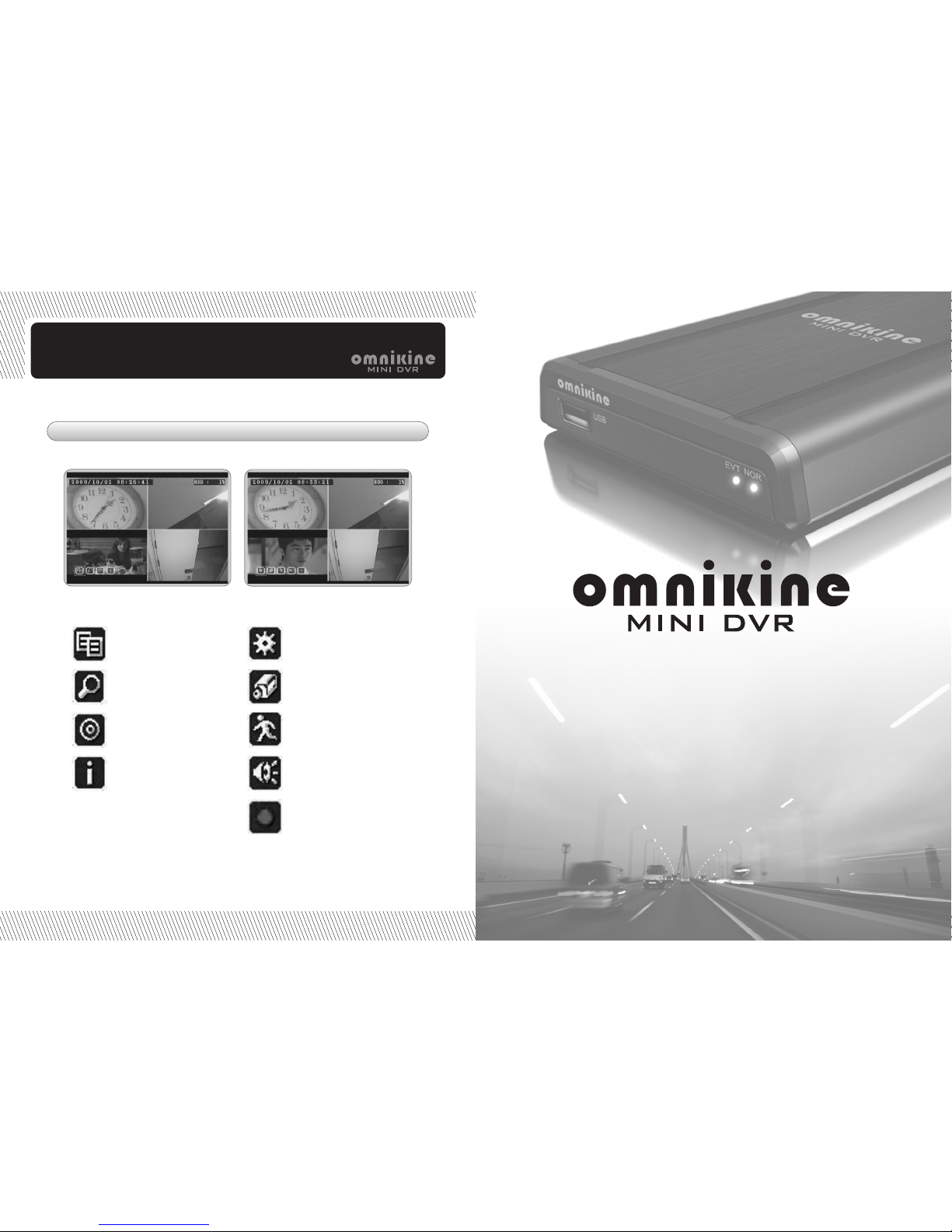
Specification
Menu Icon
Menu setup
Search
Backup
DVR Information
System setup
Camera setup
Motion setup
Audio setup
Record setup
Operation
Car & Home Security System
Indice
Manuali Sistema di sicurezza popolari di altre marche


EDM
EDM Solution 6+6 Wireless-AE Manuale utente

Highway Safety Group
Highway Safety Group EA401 Manuale utente

Siren
Siren LED GSM Manuale utente

Detection Systems
Detection Systems 7090i Istruzioni per il montaggio

Se-Kure Controls
Se-Kure Controls MicroMini SK-4841 Manuale utente

Siemens
Siemens FDM273 Manuale utente