Omron Sti H-T40M-P Manuale utente

H-T40M-P
Status Display Touchscreen
Installation and Operating Manual

2 H-T40M-P Manual Rev.A
H-T40M-P Installation & User Manual
Table of Contents
Section 1 - Important Message . . . . . . . . . . . . . . . . . . . . . page 3
Section 2 - Introduction. . . . . . . . . . . . . . . . . . . . . . . . . . . page 4
Section 3 - Safety Precautions. . . . . . . . . . . . . . . . . . . . . . page 4
Section 4 - Package Contents . . . . . . . . . . . . . . . . . . . . . . page 6
Section 5 - Specifications . . . . . . . . . . . . . . . . . . . . . . . . . page 8
Section 6 - Mounting Procedure . . . . . . . . . . . . . . . . . . . . page 10
Section 7 - Grounding . . . . . . . . . . . . . . . . . . . . . . . . . . . . page 11
Section 8 - Power Supply & Wiring . . . . . . . . . . . . . . . . . page 11
Section 9 - Dip Switches . . . . . . . . . . . . . . . . . . . . . . . . . . page 12
Section 10 - Connection to the G9SP . . . . . . . . . . . . . . . . page 12
Section 11 - Operation . . . . . . . . . . . . . . . . . . . . . . . . . . . page 13
Section 12 - Navigating the Screens . . . . . . . . . . . . . . . . . page 14
Section 13 - Screen Properties . . . . . . . . . . . . . . . . . . . . . page 19
Section 14 - Warranty & Additional Information . . . . . . . page 20

IMPORTANT MESSAGE
3 OMRON STI © 99885-0010 Rev.A
1 I
MPORTANT
M
ESSAGE
1
Please read the entire installation manual prior to installing and using this
equipment. Only qualified personnel may install, operate or repair this
equipment. Omron Scientific Technologies Inc. is not responsible for modified,
altered or renovated equipment. Because the equipment has a wide range of
applications, users must acquire the appropriate knowledge to use the
equipment properly in their specific applications. Persons responsible for the
application and the equipment must themselves ensure that each application is
in compliance with all relevant requirements, standards and legislation in
respect to configuration and safety. Only parts and accessories manufactured
according to the specifications set by Omron Scientific Technologies Inc. may
be used.
OMRON Scientific Technologies Inc. shall not be liable to anyone for any
direct, indirect, special, incidental or consequential damages resulting from the
installation, use or repair of this equipment, whether arising in tort, contract, or
otherwise. Buyer’s sole remedy shall be the replacement, or refund of purchase
price, and the choice of the applicable remedy shall be at the sole discretion of
OMRON Scientific Technologies Inc.

INTRODUCTION
2
4 H-T40M-P Manual Rev.A
2 I
NTRODUC
T
ION
2
H-T40M-P is a status display touchscreen with a 3.3” STN Liquid
Crystal Display, and is water- and dust-resistant according to IP65/
NEMA 4X (indoor use only.)
H-T40M-P is CE-marked and is highly transient-resistant while
in operation.
Also, its compact design makes connections with other machinery more
flexible, thus achieving the optimal performance for machines.
3 S
AFETY
P
RECAUTIONS
3
Both the installer and the owner and/or operator of the status display
touchscreen must read and understand this installation manual.
3.1.GENERAL
— Only qualified personnel may install or operate the status display
touchscreen
— The status display touchscreen must be installed according to the
installation instructions.
— The status display touchscreen is designed for stationary installation on a
plane surface, where the following conditions are fulfilled:
• no high explosive risks
• no strong magnetic fields
• no direct sunlight
• no large, sudden temperature changes
• for use in Pollution Degree 2 Environment
• for use on the flat surface of Types 1 and 4X (indoor use only)
enclosures
— Never allow fluids, metal filings or wiring debris to enter any openings in
the status display touchscreen. This may cause fire or electrical shock.
— The status display touchscreen fulfills the requirements of EMC directive
2004/108/EC.

SAFETY PRECAUTIONS
5 OMRON STI © 99885-0010 Rev.A
— Storing the status display touchscreen where the temperature is lower or
higher than recommended in this manual can cause the LCD display liquid to
congeal or become isotopic.
— The LCD display liquid contains a powerful irritant. In case of skin contact,
wash immediately with plenty of water. In case of eye contact, hold the eye open,
flush with plenty of water and get medical attention.
— The supplier is not responsible for modified, altered or reconstructed
equipment.
— Use only parts and accessories manufactured according to specifications of
the supplier.
— Peripheral equipment must be appropriate for the application and location.
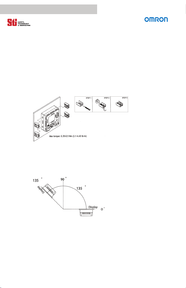
— The figures in this manual serve an illustrative purpose. Because of the many
variables associated with any particular installation, the supplier cannot assume
responsibility for actual use based on the figures.
— The supplier neither guarantees that the status display touchscreen is suitable
for a customer’s particular application, nor assumes responsibility for a customer’s
product design, installation or operation.
3.2.POWER SOURCE
The status display touchscreen is equipped with a 24VDC input. Supplying
power other than 24VDC +/- 15% will severely damage the status display
touchscreen. Thus, check the power supply supporting the DC power
regularly.
3.3.GROUNDING
Without grounding, the status display touchscreen may be severely affected
by excess noise. Make sure that the grounding is done properly from the
power connector at the rear side of the status display touchscreen. When
power is connected, make sure that the wire is grounded.
Use a cable of at least 2mm2(AWG 14) to ground the status display
touchscreen. Ground resistance must be less that 100 Ω(class 3). Note that
the ground cable must not be connected to the same ground point as the power
circuit.
3.4.INSTALLATION
Communication cables must be separated from power cables for operational
circuits. Only use shielded cables to avoid unpredictable problems.

PACKAGE CONTENTS
4
6 H-T40M-P Manual Rev.A
3.5.DURING USE
• Emergency stop and other safety functions may not be controlled from the
status display touchscreen.
• Do not use too much force or sharp objects when touching the keys, display,
etc.
3.6.SERVICE AND MAINTENANCE
Only qualified personnel should carry out repairs.
• The agreed warranty applies.
• Before carrying out any cleaning or maintenance operations, disconnect the
equipment from the electrical supply.
• Clean the display and surrounding front cover with a soft cloth and mild
detergent.
• Replacing the battery incorrectly may result in explosion. Only use batteries
recommend by supplier.
3.7.DISMANTLING AND SCRAPPING
• The status display touchscreen or parts thereof shall be recycled according
to local regulations.
• The following components contain substances that might be hazardous to
health and the environment: lithium battery, electrolytic capacitor and
display.
4 P
ACKAGE
C
ONTENTS
4
The following parts are found in the box:
•(1) Status Display Touchscreen H-T40M-P
• (4) Installation fasteners
• (1) Power connector (connected to 24VDC power input)
• (1) Communication cable from HMI status display touchscreen to G9SP

PACKAGE CONTENTS
7 OMRON STI © 99885-0010 Rev.A
Figure 4-1 Status Display Touchscreen H-T40M-P
Figure 4-2 Installation Fasteners
Figure 4-3 Power connector

SPECIFICATIONS
5
8 H-T40M-P Manual Rev.A
5 S
PECIFICATIONS
Parameter H-T40M-P
Front panel W x H x D 96.0 x 96.0 x 7.0 mm
Mounting Depth 40.6 mm
Cut out dimensions 89.3 x 89.3 mm
Front panel seal IP 65 / NEMA 4X (indoor use only)
Weight 0.21 kg
COM 1 9-pin female connector: RS232
Screen Size 3.3” diagonal
Display Mono FSTN LCD, 16 shades of gray
Pixels 240 x240 pixels
Back light type LED
Back light lifetime 10,000 hours
Touch screen operations > 1,000,000
Active area of display W x H 58.5 x 58.5 mm
Brightness (cd/m2) 110
Processor 32 - bit RISC
Status LED PWR, COM1
Storage temperature -10 to +60 C
Relative operating humidity 20 - 90% RH
Vibration 0.5 displacement, 10-55Hz, 2 hours X-, Y-,
Z-axis
Shock resistance 10G, 11ms 3 times in each direction of X-,
Y-, Z-axis
Cooling Natural Cooling
Electrostatic discharge IEC 61000-4-2
RF susceptibility IEC 61000-4-3
High frequency transients IEC 61000-4-4
CE approvals EN 6100-6-4, EN 6100-6-2
RF emissions CISPR 22, Class A
5
5.1.TECHNICAL SPECIFICATIONS
Table 5-1 Product Specifications

SPECIFICATIONS
9 OMRON STI © 99885-0010 Rev.A
5.2.DESCRIPTION OF THE PARTS
Figure 5-1 H-T40M-P Mechanical Drawing
5.3. EXTERNAL AND CUT-OUT DIMENSIONS
Figure 5-2 External and Cut-out Dimensions

MOUNTING PROCEDURE
6
10 H-T40m-P Manual Rev.A
6 M
OUNTING
P
ROCEDURE
6
1. Cut out the control front panel to match the dimensions (mm) specified
in the External and Cut-out-Dimensions section.
2. Mount the status display touchscreen into the cut-out. Insert the fixtures
to the holes on the unit and fasten the screws into the front of the panel. Do
not tighten the screws with too much or uneven force or it may cause the
deformation of the status display touchscreen.
Figure 6-1 Mounting
3. The status display touchscreen is to be installed within the angle of 0 to
135° as shown below.
Figure 6-2 Install Angle
Indice
Manuali Schermo tattile popolari di altre marche

Elecro Engineering
Elecro Engineering Poolsmart Plus Istruzioni per l'installazione

Johnson Controls
Johnson Controls IQ4 HUB Manuale utente

Elo TouchSystems
Elo TouchSystems ET2270L Manuale utente

Elo TouchSystems
Elo TouchSystems ET1002L Manuale utente

Elo TouchSystems
Elo TouchSystems 3201L Manuale utente

Duratec
Duratec S15 Manuale utente


