Origin 21 LWS35KCR Manuale utente

1
KITCHEN CART WITH
RUBBERWOOD TOP
ITEM #4350898
MODEL #LWS35KCR
AS21712
Français p. 12
Español p. 23
Serial Number Purchase Date
ATTACH YOUR RECEIPT HERE
ORIGIN 21 and logo design are trademarks or registered
trademarks of LF, LLC. All rights reserved.
Questions, problems, missing parts? Before returning to your retailer, call our customer service
department at (888) 251-1026, 8 a.m. - 8 p.m., EST, Monday - Sunday. You could also contact us at
2
TABLE OF CONTENTS
Camlock System Operation............................................................................................... 2
Package Contents............................................................................................................... 3
Hardware Contents...............................................................................................................4
Safety Information............................................................................................................... 5
Preparation ......................................................................................................................... 5
Assembly Instructions.......................................................................................................... 6
Care and Maintenance ....................................................................................................... 9
Limited Lifetime Warranty.................................................................................................. 9
Replacement Parts List ................................................................................................... 10
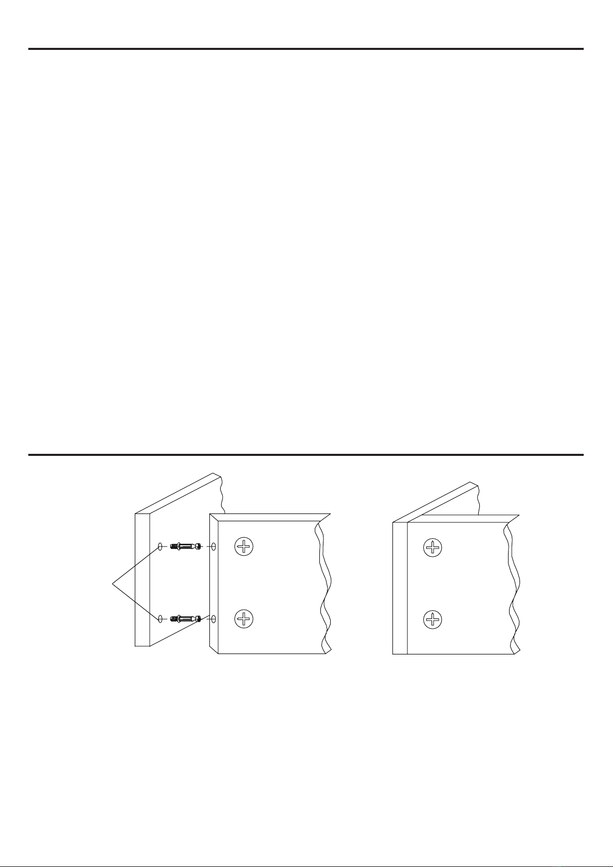
CAM LOCK SYSTEM OPERATION
1. Screw cam bolts into the predrilled small holes on panel.
2. Insert cam lock into predrilled large hole on panel.
3. Make sure the arrow on the cam lock is pointed toward the cam bolts.
4. Connect both panels together, making sure cam bolts goes into predrilled hole on
the end of panel with cam lock.
5. Once cam bolts is connected inside cam lock, take Phillips screwdriver and tighten
cam lock clockwise.
DETAIL A DETAIL B
THREADED
INSERT
LOCKED POSITION
PANELPANEL
Cam Bolts
CAM LOCK
3
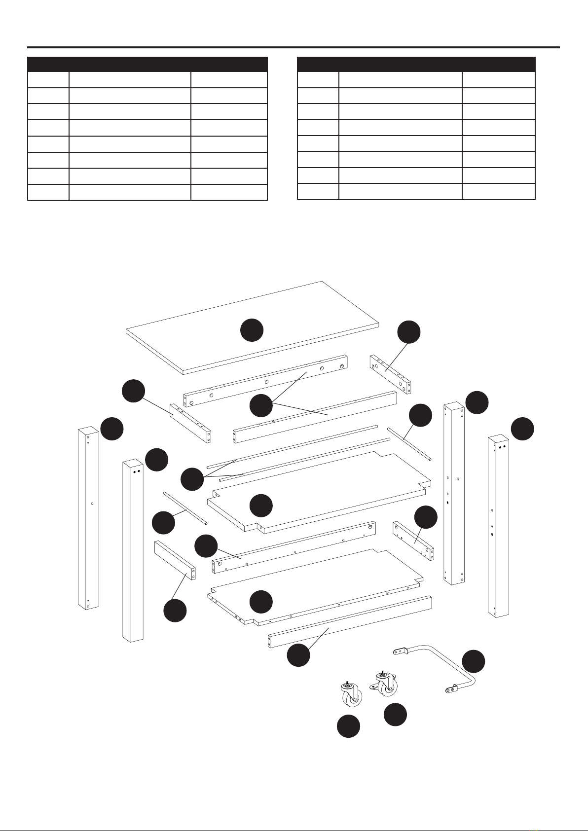
PACKAGE CONTENT
PART DESCRIPTION QUANTITY
A Top Panel 1
B Left Back Post 1
C Left Front Post 1
D Right Back Post 1
E Right Front Post 1
F Upper Stretcher 2
G Upper Side Stretcher 2
H Long Metal Stretcher 2
PART DESCRIPTION QUANTITY
I Short Metal Stretcher 2
J Shelf 1
K Lower Stretcher 2
L Lower Side Stretcher 2
M Bottom Panel 1
N Handle 2
O Caster 2
P Caster With Brake 2
A
F
C
D
I
I
J
N
E
H
G
G
L
L
M
OP
B
K
K

4
HARDWARE CONTENTS (shown not actual size)
Cam Bolt
Qty. 36
1/4” Lock Washer
Qty. 4
L metal plate
Qty. 4
AA
FF
II
BB
GG
JJ
DD
CC
HHEE
KK LL
Cam Lock
Qty. 36
1/4” Flat Washer
Qty. 4
PVC Cover
Qty. 26
M4 x 17mm Screw
Qty. 8
Wood Dowel
Qty. 36
1/4”x 15 mm
Sala Bolt
Qty. 8
1/4”x 15 mm Bolt
Qty. 4
Allen Wrench
Qty. 1
Touch up Pen
Qty. 1

5
PREPARATION
Please read the instruction sheets completely before assembly. Examine all packaging material before
discarding carton. Remove any remaining staples from the carton before discarding. Remove all parts
from carton and separate into groups as indicated on part list. Please ensure all parts are included
prior to assembly. Use of power tools must be with caution and ensuring setting at low-torque, avoid
damaging the wood panels.
Estimated Assembly Time: 60 minutes.
Tools Required for Assembly: Phillips screwdriver, stud nder, marking pencil, tape measure, power
drill and drill bits.
SAFETY INFORMATION
Please read and understand this entire manual before attemting to assemble or install the product.
1. Please read the Assembly Instructions prior to assembling the unit.
2. To avoid damage, assemble the unit on a sturdy, level and non-abrasive surface.
3. Keep all hardware and parts out of the reach of children.
4. Please wait until all steps are completed before fully tightening bolts.
5. Make sure all bolts and screws are tightly fastened before the unit is used.
6. Check that all bolts, screws are tight at least every 3 months or as needed.
WARNING
THIS UNIT IS INTENDED FOR USE ONLY WITH THE MAXIMUM WEIGHTS INDICATED. USE
WITH PRODUCTS HEAVIER THAN THE MAXIMUM WEIGHTS INDICATED MAY RESULT IN
INSTABILITY CAUSING POSSIBLE INJURY. DISTRIBUTE WEIGHT EVENLY.
TOP MAXIMUM:
45.4kg / 100 lb
EVENLY DISTRIBUTED.
SHELF MAXIMUM:
13.6kg / 30 lb
EVENLY DISTRIBUTED.
ENTIRE UNIT MAXIMUM
WEIGHT CAPACITY:
72.7kg / 160 lb
EVENLY DISTRIBUTED

6
ASSEMBLY INSTRUCTIONS
Hardware Used
1
2
3
2. Attach lower stretcher (K) to bottom panel (M) using
wood dowels (CC) and cam locks (BB).
3. Attach left back post (B), upper side stretcher (G), short
metal stretcher (I), and lower side stretcher (L) to left front
post (C), attach right back post (D), upper side stretcher
(G),short metal stretcher (I), and lower side stretcher (L) to
right front post (E), using wood dowels (CC) and cam locks
(BB).
Hardware Used
1. Insert cam bolts (AA) into left back post (B), left front
post (C), right back post (D), right front post (E), lower
stretcher (K), and lower side stretcher (L).
AA Cam Bolt x 26 B
E
C
E
D
K
L
K
M
B
C
K
L
L
G
G
I
D
AA
BB
CC
CC BB
BB
BB
CC
CC
Cam Lock
Cam Lock
Wood Dowel
Wood Dowel
x 6
x 8
x 4
x 8
I
Hardware Used

7
ASSEMBLY INSTRUCTIONS
4
5
6
Hardware Used
Hardware Used
Hardware Used
4. Insert cam bolts (AA) into top panel (A) .
5. Install the L metal plate (II) to pilot hole of the shelf (J),
tighten with screws (DD).
6. Attach left back post (B), left front post(C), upper stretch-
er (F), long metal stretcher (H), shelf (J) and lower stretcher
(K), bottom panel (M) to right back post (D), right front post
(E),using wood dowels (CC) and cam locks (BB).
DD
II
M4 x 17 mm Screw
L Metal Plate
x 8
x 4 J
A
AA
II
DD
BB
CC
B
F
H
J
KM
C
E
D
AA Cam Bolt x 10
BB
CC
Cam Lock
Wood Dowel
x 12
x 16

8
ASSEMBLY INSTRUCTIONS
7
8
9
7. Attach left back post (B), left front post (C), upper stretcher
(F), upper side stretcher (G), right back post (D), right front
post (E) to top panel (A), using wood dowels (CC) and cam
locks (BB).
9. Using allen wrench (KK) and 1/4” x 15 mm sala bolt (HH)
to tighten handle(N) on left back post (B), left front post(C),
right back post (D), right front post (E).
All expose cam lock holes covered with PVC cover (JJ)
8. Intall caster (O) and caster with brake (P) into the bottom
of post T- nut.
Using allen wrench (KK), 1/4” x 15 mm bolt (EE), 1/4” lock
washer (FF), 1/4” at washer (GG) to tighten shelf (J) on the
post.
HH
KK
JJ
FF GG
EEKK
CC BB
B
G
A
N
O P
J
D
E
F
E
C
Hardware Used
Hardware Used
BB
CC
Cam Lock
Wood Dowel
x 10
x 8
C
D
B
EE
FF
GG
HH
KK
1/4”x 15 mm Bolt
1/4” Lock Washer
1/4” Flat Washer
1/4”x 15 mm Sala Bolt
Allen Wrench
x 4
x 4
x 4
x 8
x 1
Hardware Used
JJ PVC cover x 26
KK Allen Wrench x 1

9
CARE AND MAINTENANCE
• Use a soft, clean cloth that will not scratch the surface when dusting.
• Use of furniture polishes is not necessary. Should you choose to use polishes, test rst in an
inconspicuous area.
• Using solvents of any kind on your furniture may damage the nish.
• Never use water to clean your furniture as it may cause damage to the nish.
• Always use coasters under beverage glasses and owerpots.
• Liquid spills should be removed immediately. Using a soft clean cloth, blot the spill gently. Avoid
rubbing.
• Always use protective pads under hot dishes and plates. Heat can cause chemical changes that
may create spotting within the furniture nish.
• Stains or marks from crayons or ink markers will be dicult to remove.
• In the event that your furniture is stained or otherwise damaged during use, we recommend that
you call a professional to repair your furniture.
• Check bolts/nuts periodically and tighten them if necessary.
• Touch-up Pen (LL) has been provided to repair any small nicks or scratches that may occur
during assembly or shipping.
LIMITED LIFETIME WARRANTY
This product is warranted to the original purchaser. If there is a failure in this unit due to defects
in materials or workmanship, the manufacturer will repair or replace this item at our discretion
without charge. Warranty is void if product has been assembled incorrectly, misused, abused by
overloading, altered in any way or damaged due to accident. This warranty is not transferable and
does not cover chipping, aking, scratches, rust, dents, or other damages to the surfaces of this
product. Responsibility of the manufacturer is limited to repair or replacement of this product. The
manufacturer is not responsible for consequential, incidental, or other damages or losses resulting
from product failure.
This warranty is in lieu of all other expressed warranties. Some states do not allow the exclusion or
limitation of incidental or consequential damages, so the above limitation may not apply to you. This
warranty gives you specic legal rights and you may have other rights which vary from state to state.

10
PART DESCRIPTION PART #
A Top Panel 00LWS35KCR-01
B Left Back Post 00LWS35KCR-02
C Left Front Post 00LWS35KCR-03
D Right Back Post 00LWS35KCR-04
E Right Front Post 00LWS35KCR-05
F Upper Stretcher 00LWS35KCR-06
G Upper Side Stretcher 00LWS35KCR-07
H Long Metal Stretcher 00LWS35KCC-CR-08
I Short Metal Stretcher 00LWS35KCC-CR-09
J Shelf 00LWS35KCR-10
K Lower Stretcher 00LWS35KCR-11
L Lower Side Stretcher 00LWS35KCR-12
M Bottom Panel 00LWS35KCR-13
N Handle 00LWS35KCC-CR-14
O Caster 00LWS35KCC-CR-15
P Caster With Brake 00LWS35KCC-CR-16
AA Cam Bolt 00LWS35KCC-CR-17
BB Cam Lock 00LWS35KCC-CR-18
CC Wood Dowel 00LWS35KCC-CR-19
DD M4 x 17mm Screw 00LWS35KCC-CR-20
EE 1/4”x 15 mm Bolt 00LWS35KCC-CR-21
FF 1/4” Lock Washer 00LWS35KCC-CR-22
GG 1/4” Flat Washer 00LWS35KCC-CR-23
HH 1/4”x 15 mm Sala Bolt 00LWS35KCC-CR-24
II L metal plate 00LWS35KCC-CR-25
JJ PVC Cover 00LWS35KCC-CR-26
KK Allen Wrench 00LWS35KCC-CR-27
LL Touch up Pen 00LWS35KCC-CR-28
REPLACEMENT PARTS LIST
For replacement parts, call our customer service department at (888) 251-1026, 8 a.m. - 8 p.m., EST,
com.
Questo manuale è adatto per i seguenti modelli
1
Indice
Lingue:


