OXYDrive RC11Ah Manuale utente

Electric Bike Conversion Kit
Installation’s Manual
V.1.6
May 2015
2
Table of contents:
Page
1. Beforeinstallation 3
2. Recommendation for washing 3
3. Installing the motor 3
4. Installing the battery unit 6
5. Installing the pedal assist sensor 7
6.FittingtheLCDconsole 9
7. Installing the brake cut off switches 10
8. Connecting the connectors 11
9. Connecting brake lever & throttle to the LCD 12
This manual applies to the OXYDrive RC11Ah conversion kit.
PLEASE NOTE: Not all the illustrations may apply to your specific
kit. This is a DIY conversion kit and some illustrations may vary
from the actual product purchased. The entire concept of fitting is
the same on all kits. Also note that installation on various bikes
may vary and there may be a need to take an individual approach
for every bike conversion. OXYDrive does not take any liability for
the damages caused to the bike frames or any other bike
components. The conversion kits are fitted at owner’s risk.

3
1. Before installation
Before installing this kit please note that there is a minimum skills
required to run a successful installation. If the end user feels
uncomfortable to carry on the assembly process it is advised to take it
to the nearest dealer or good bicycle shop with workshop facilities. To
run a successful installation the assembler will need the basic
workshop tools too. Please read the next chapter
2. Tools required for installation
All good bicycle workshops will have all necessary tools to carry on the
assembly process:
Tools required for installation:
- Set of allen (hex) keys, 2-6mm
- Cable cutters
- Crank puller
- Bottom Bracket Tool
- 15mm spanner (wrench)
- Set of tyre levers
- Bicycle pump
- Flat and cross screwdrivers
3. Installing the motor
Step 1
Fit the bicycle tyre along with the rim tape to the new OXYDrive wheel.
Step 2 Fitting front wheel motor
Try to slot the motor into the forks drop outs. Please note that some forks may
only have a 9mm drop outs. The motor axle is 10mm and therefore may not fit.
IMPORTANT: The motor’s axle must slot in to the dropouts easily with
no use of any force. If you fork drop out is too narrow please use a file
to file off the surface by 0.5 mm on each side.
4
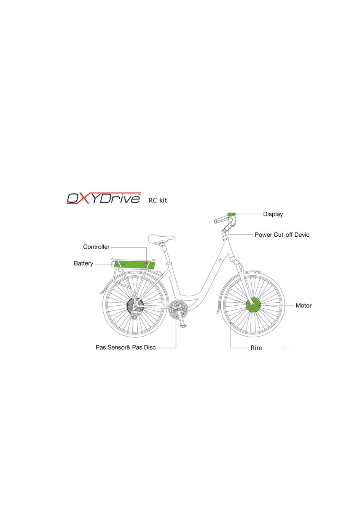
Step 4.
It is crucial to pay extra attention to the order of fitting the locking
nuts. Always use good quality 15mm spanner to secure the wheel
5
IMPORTANT: The locking nuts should be regularly checked
every few rides to ensure the wheel is securely fitted.
4. Installing the battery unit
6
The battery holding unit with the rear carrier should be fitted to the
frame mounts for rear carriers. Majority of frames have a special
mounts where the rear rack can be attached to. Please make sure the
bolts are well screwed in to the frame at it’s full length of thread.
This manual does not give any recommendations on the bolts size or
torque as it all depends on the each individual frame requirements.
Please note that rear rack unit should be well secured to the frame.
The battery should be slotted on the holder’s rail locked with the key.
7
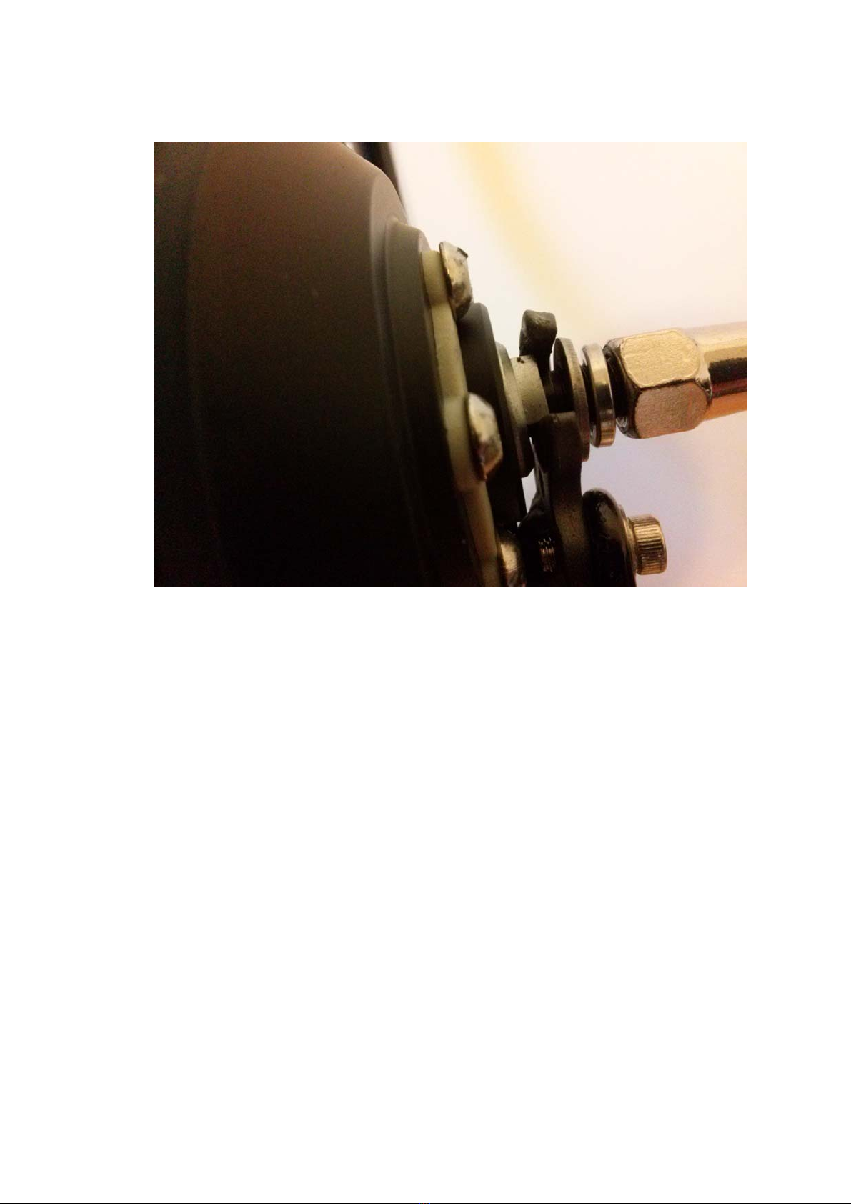
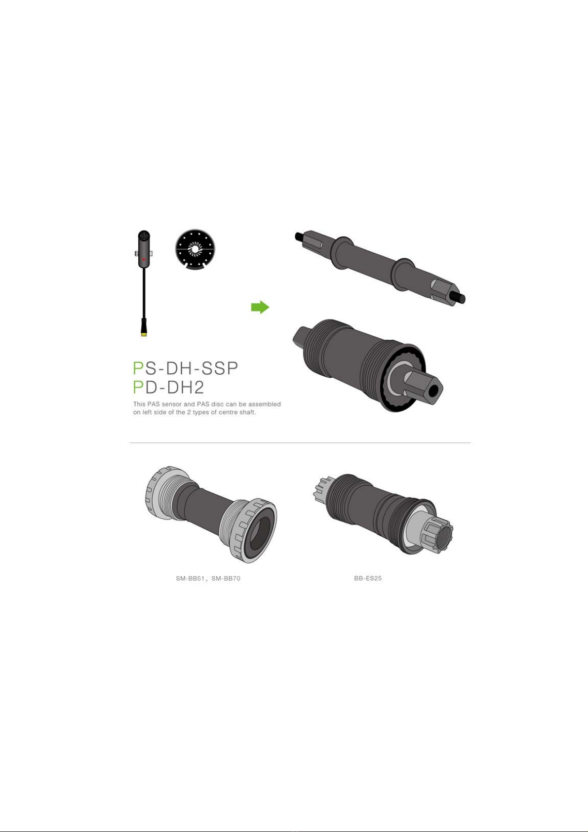
5. Installing pedal assist sensor
The speed sensor that comes with the kit is designed to be fitted on
the left hand side of the bottom bracket. It perfectly fit square taper
axles but with minor modifications this can also be fitted to Shimano
Octalink or ISIS drives.
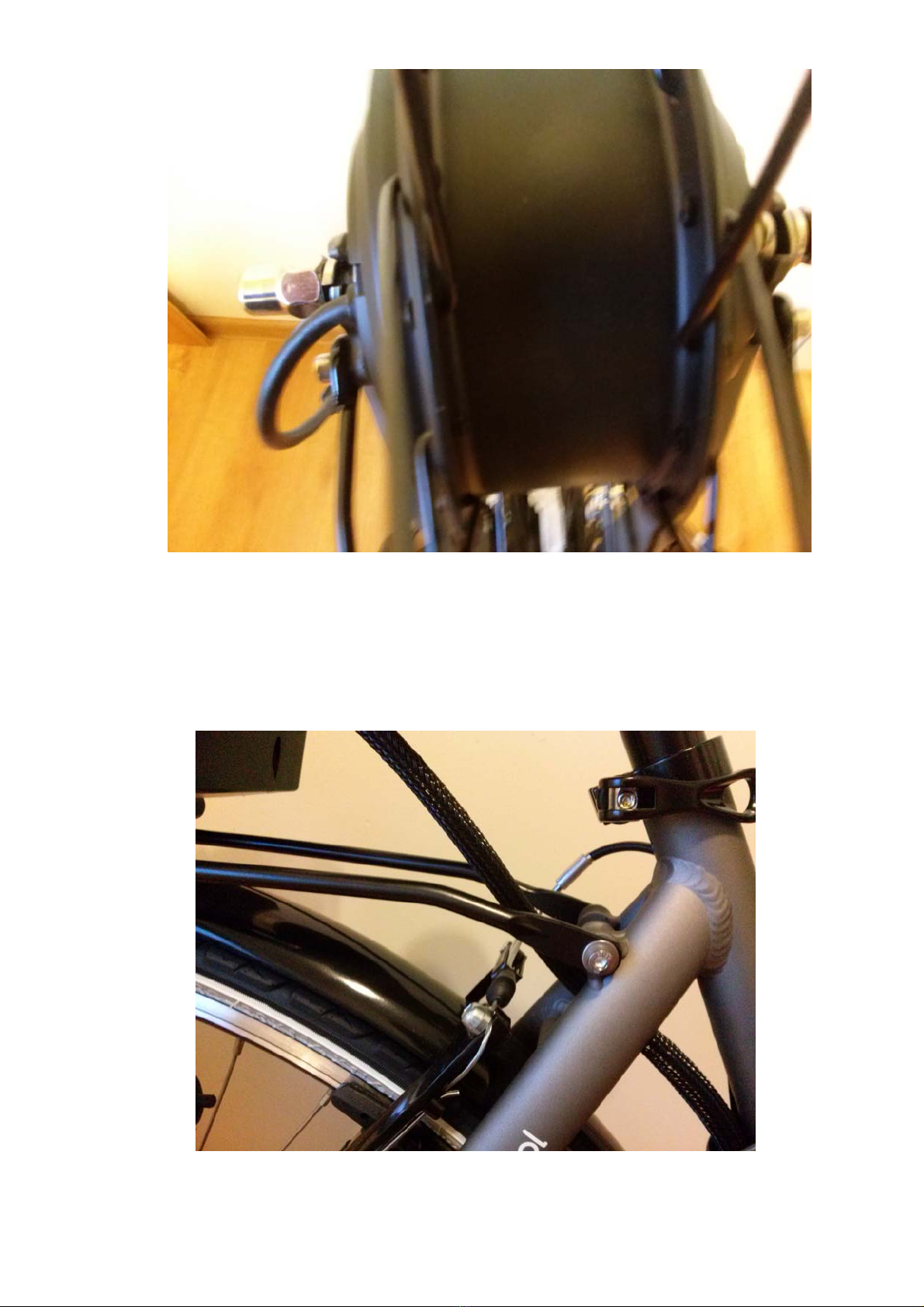
For Octalink and ISIS the standard magnet needs the internal hole to
be enlarged. To do that it’s best to file it of.

8
The magnet disc should be fitted on the axle with magnets located
approx 1-3mm from the speed sensor.
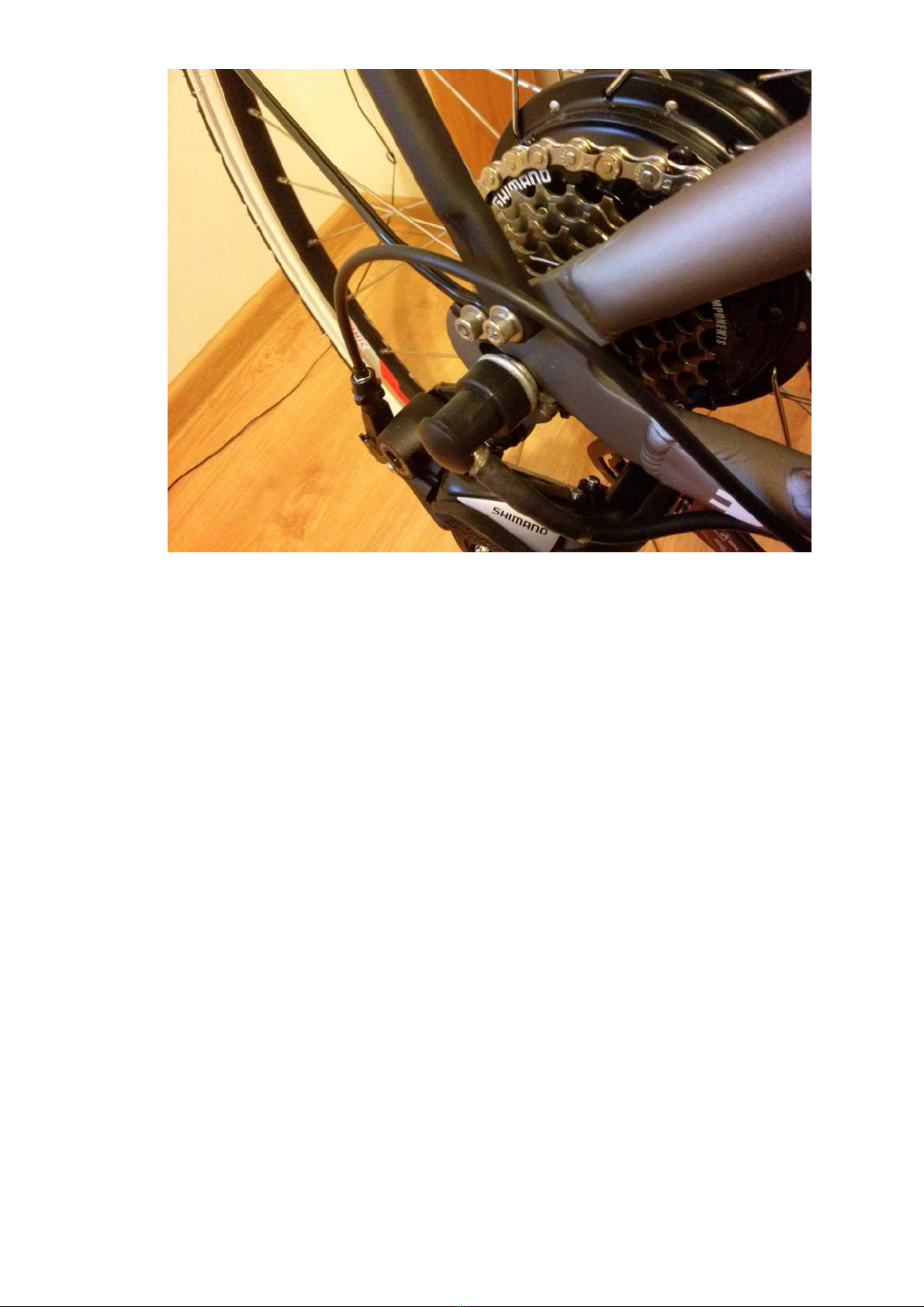
IMPORTANT: OXYDrive PAS sensor provided is currently compatible
with the square tapered bottom brackets. In some case if the axle is
too short or there is not enough room the bottom bracket might need
to be replaced for the one with longer axle. This can be modified to fit
Octalink and ISIS and Hollowtech cranks but if you have one of these
systems please contact us about availability of special Octalink,
Hollowtech sensors.

9
6. Fitting the LCD console
Currently there are two displays available for OXYDrive kits. C300 with
buttons integrated in the display should be fitted on the left hand side.
In order to fit this display the handlebar grip, shifters and brake lever
should be removed and the display should be slotted on the
handlebars.
There is also another way of fitting this display by removing off the
display the holding bracket and slotting it back when display is already
on the handlebars.
10
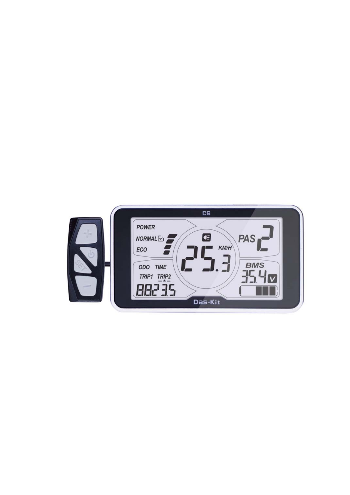
FIITING THE CENTRAL DISPLAY C6
In order to fit this display the handlebar grip, shifters and brake lever
should be removed and the display should be slotted on the
handlebars. The display should be located centrally in the middle of the
handlebars.
Fitting the throttle and the power setting buttons will depend on the
type of the bike and this has to be tried by each user. Throttle can be
located on either left or right hand side of the handlebars. If fitted on
the left the thumb twist will have to move forward then.
Indice


