
PENSOTTI PCH 34B H Manuale

Pensotti ASME Condensing Boilers
Cleaning Procedure
Version 1 - All Models
1

2
Pensotti ASME Condensing Boilers
Table of Contents
Service Requirements Pg. 3
Safety Precautions Pg. 5
Combustion Chamber Cleaning Procedure Pg. 7
Diverter Valve Lubrication Pg. 29
Water Test and Treatment Pg. 30
Version 1

To maintain reliability, efficiency and safe operation, it is imperative that all models of Pensotti
Condensing Gas Boilers be cleaned and inspected by a trained, licensed technician on an annual
basis.
3
Service Requirements
Version 1
To maintain the highest possible operating efficiency, the heat exchanger surfaces must be kept clean. Soot and foreign debris will
insulate the heat exchanger surface, reducing the efficient transfer of heat. Failure to inspect and clean the heat exchanger annually
can result in the following problems:
•Plugged combustion passages
•Reduced heating capacity
•Increased flue gas temperatures
•Flue gas thermo-fuse failures, generating an E03 Error Code
•Rough ignition
•Ignition failure, generating an E01 Error Code
•Ignition electrode failure
•Ionization rod failure
•Pulsating combustion
•Heat exchanger failure
Contributing factors to the build up of soot and foreign debris on the heat exchanger surface are:
•Improper burner adjustment
•Improper conversion to the operating fuel
•Combustion air quality
•Cross-contamination of the flue gas and combustion air
•Amount of burner run time
•Frequency of burner on-off cycles
•Amount of condensation generated during operation
•Sulfur content of the fuel

4
Service Requirements
Version 1
The quantity and rate of build-up on the heat exchanger will vary with each boiler installation due to the factors mentioned on page 3.
Boilers operating on LP Gas and those installed in environments containing high levels of pollutants or chemical vapors in the
combustion air may need to be cleaned more frequently. The frequency of a cleaning schedule will need to be determined by the
servicing company based on the condition of the heat exchanger at the time of cleaning.
Dirty Heat Exchanger Blocked Heat Exchanger Passages

Safety Precautions
5Version 1
Important Personal Protective Equipment is recommended when handling the insulating material (Refractory Ceramic Fibers)
on the burner door and back wall of the combustion chamber.
Warning Refractory Ceramic Fibers in high temperature applications can result in the formation of Crystalline Silica Dust.
Repeated airborne exposure of Crystalline Silica Dust may result in chronic lung infections, respiratory illness, or
death. Crystalline Silica is listed as a potential, occupational carcinogen by the following organizations: OSHA, NIOSH,
International Agency for Research on Cancer (IARC), and Canadian Centre for Occupational Health and Safety
(CCOHS). Certain components contained within the combustion chamber of this boiler may contain this potential
carcinogen. Improper service, maintenance, alteration, or adjustment can cause property damage, serious illness or
death. Service of this boiler must be performed by a qualified technician, service agency or gas supplier who has
read and understands the instructions and information provided.
Warning Handling Instructions for Refractory Ceramic Fibers
Exposure Risk Precautions and Recommended Personal Protective Equipment
Prevent contact with skin and eyes •Wear safety glasses or googles
•Wear gloves
•Wear long sleeve shirts and pants
•Wear a disposable cover-all
Prevent breathing of silica dust •Wear an approved respirator with N95 rated filter or better
•Use a water mist to minimize airborne dust particles when cleaning and serving the
combustion chamber
•Do not sweep dust particles. Spray with a water mist then collect with damp rags or
a vacuum with a high efficiency filter.
Prevent transfer of silica dust •Transfer Refractory Ceramic Fiber items, both new and used in sealed plastic bags.
•Remove contaminated clothing immediately and store in a sealed plastic bag.
•Launder contaminated clothing separately
•Dispose of disposable articles of clothing correctly
First Aid •Inhalation –Move to fresh air. Sneeze, cough and blow nose to clear irritated
passageways. Drink plenty of water.
•Skin –wash all affected areas with generous amounts of soap and water.
•Eyes –Flush with clean water immediately. Do not rub eyes.
If irritation persists, contact a physician immediately

Safety Precautions
6Version 1
Important Follow all instructions, failure to do so could result in personal property damage, injury or death. Refer to the
installation manual, supplied with the boiler, for additional information.
Warning
Warning
If you smell gas:
•Do not operate any appliance
•Do not attempt to light any gas appliance
•Do not turn any electrical switches on or off
•Do not use any phone in the building, land line or cell
•Leave the building and call the gas supplier from a neighbors phone or from a safe distance with a cell phone
•If the gas supplier can not be reached call the local fire department or dial 911
•Do not re-enter the building
Do not operate this boiler if any part had been under water. Replace each item in the control system that has been
under water. Replace the gas valve if its been under water. Failure to replace these items could result in; personal
property damage, personal injury, explosion or death.
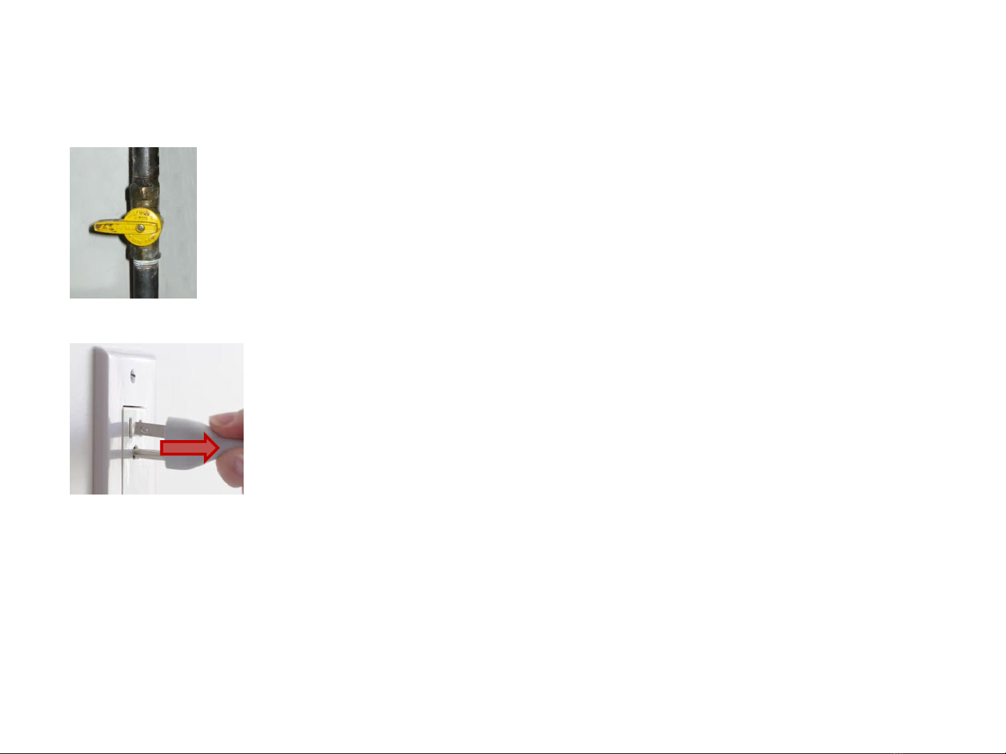
Important Before performing a cleaning and inspection:
•Turn off all electrical power to the boiler
•Remove the power cord from the electrical outlet
•Turn the manual gas shut off valve, in the gas line of the boiler, to the closed position
•Prepare a clean, safe work area around the boiler
Warning Do not operate this boiler if any parts are found to be damaged, corroded or defective. Replace each item before
operating the boiler. Failure to replace these items could result in; personal property damage, personal injury, explosion
or death.
Warning Inspect the venting system:
•Verify the condition of all the vent system components are in good repair
•Inspect the location of the vent termination on the outside of the building
•Verify that all vent system components are secured together with a minimum of 2 screws
•Replace any damaged or defective vent component before operating the boiler
•Failure to replace these items could result in; personal property damage, personal injury, explosion or death.
7
Combustion Chamber Cleaning Procedure
Version 1
1. Turn the manual gas shut off valve, for the boiler, to the closed position
2. Disconnect electrical power to the boiler. Remove the electrical cord from the outlet
3. Remove the front cover of the boiler
•Models PCC34, PCH18B, PCH34B and PCI18/8: Remove the 2 Philips head screws on the bottom edge of the front cover (screws face
the floor). Pull the bottom edge of the cover away from the boiler, then lift up to release the top edge.
•Model PCH50B: Remove the single Philips screw from the top edge of the cover (screw faces the ceiling). Grasp both the top and
bottom of the cover firmly and pull. The cover is secured with male/female spring clips.
•Model PCI34/20: Remove the single Philips screw from the top edge of the cover (screw faces the ceiling). Grasp both the top and
bottom of the cover firmly and pull. The cover is secured with male/female spring clips. Remove the 4 Philips head screws that retain
the silver cover. The top 2 screws also secure the front covers retaining bracket. Grasp the right side of the silver cover securely and
pull it away from the boiler at a 45 degree angle, then pull the left side away from the boiler.

8
Combustion Chamber Cleaning Procedure
Version 1
4. Disconnect:
•The ionization electrode cable from the electrode - A
•The ignition electrode cable from the ignition transformer - B
•The ground wire from the ignition electrode - C
•The cable on the gas valve - D
•The pressure switch hose from the gas venturi - E
•The 2 cables connected to the fan motor - F
•PCH50B ONLY remove the combustion air tube from the gas venturi by loosening the clamp
F
E
D
C
B
A

Version 1 9
Combustion Chamber Cleaning Procedure
F
F
E
D
Version 1 10
Combustion Chamber Cleaning Procedure
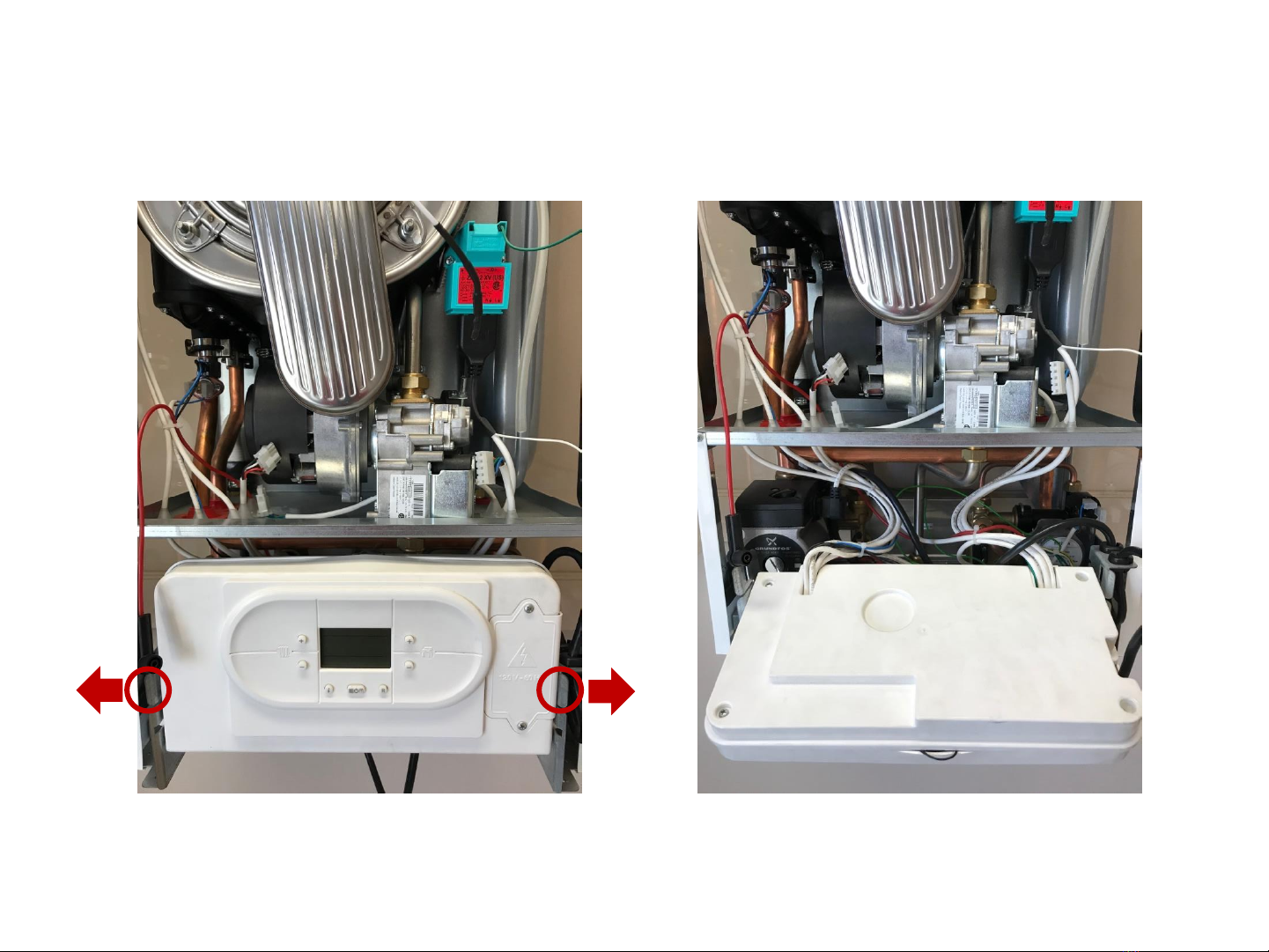
5. Flip the control panel down by spreading the 2 retaining bracket handles
Questo manuale è adatto per i seguenti modelli
9
Indice
Altri manuali PENSOTTI Caldaia

PENSOTTI
PENSOTTI DK2-3 Manuale utente

PENSOTTI
PENSOTTI PCH 50B-H Manuale utente

PENSOTTI
PENSOTTI DK2 Series Manuale utente

PENSOTTI
PENSOTTI SOLENNE SERIES Manuale utente

PENSOTTI
PENSOTTI PCC 34-H Manuale utente

PENSOTTI
PENSOTTI PCH 50B-H Manuale utente

PENSOTTI
PENSOTTI PCI 20-H Manuale utente

PENSOTTI
PENSOTTI PNCC-32N Manuale utente

PENSOTTI
PENSOTTI PCH 18 Manuale utente

PENSOTTI
PENSOTTI PCH 34B-H Manuale utente


