
Perle eX-(1/4)S110-RJ Manuale utente
Perle Standalone
1 port and 4 port
Ethernet Extenders
Installation Guide
10/100 10/100/1000 (Gig)
eX-(1/4)S110-RJ eX(1/4)S1110-RJ
eX(1/4)-1S110-BNC eX(1/4)S1110-BNC
eX-(1/4)S110-TB eX(1/4)S1110 -TB
eX-(1/4)S110-RJ-XT eX-(1/4)S1110-RJ-XT
eX-(1/4)S110-BNC-XT eX-(1/4)S1110-BNC-XT
eX-(1/4)S110-TB-XT eX-(1/4)-S1110-TB-XT
Part# 5500330-11

Perle 10/100/1000 Ethernet Extenders
2
Overview
This document contains instructions necessary for the installation
and operation of the Perle Gigabit and 10/100 Ethernet
Extenders. These Ethernet Extenders enable Ethernet
communication across a single pair of copper wires such as 2-
wire twisted pair telephone wire or coax cable using VDSL2
technology. They extend Ethernet beyond the 328-foot (100-
meter) limitation up to 3 kilometres (1.86 miles).
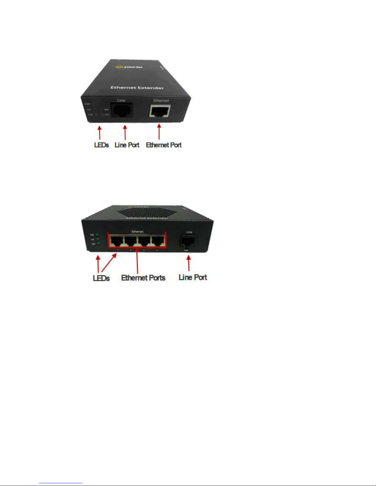
Perle Ethernet Extenders are available in 1 port or 4 port models.
Models can be ordered with a RJ45, BNC or Terminal Block
connector and also come in Extended Temperature models (XT).
Installation
The default Dip switch settings (all switches in the UP position)
will work for most installations, however it is recommended that
one Ethernet Extender should be configured for Auto Local mode
(Auto CO) and the other Ethernet Extender be configured for
Remote mode (CPE).
These are the steps required to configure a pair of Perle Ethernet
Extenders:
1.
Set the Dip switch on each Ethernet Extender. (optional)
2.
Connect a Line cable to the port labelled as Line. VDSL
Interfaces for more information).
3.
Connect Ethernet cable(s) to the port(s) labelled as
Ethernet.
4.
Connect power to the Ethernet Extenders.
Perle 10/100/1000 Ethernet Extenders
3
Front Panel Views
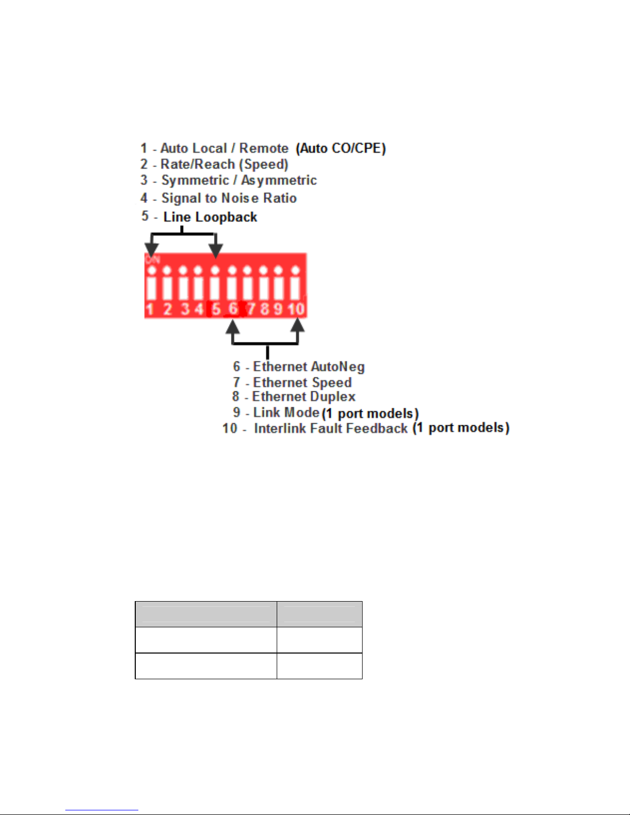
Figure 1 - Ethernet Extender 1 Port
Figure 2 - Ethernet Extender 4 port (Extended Temperature)
Perle 10/100/1000 Ethernet Extenders
4
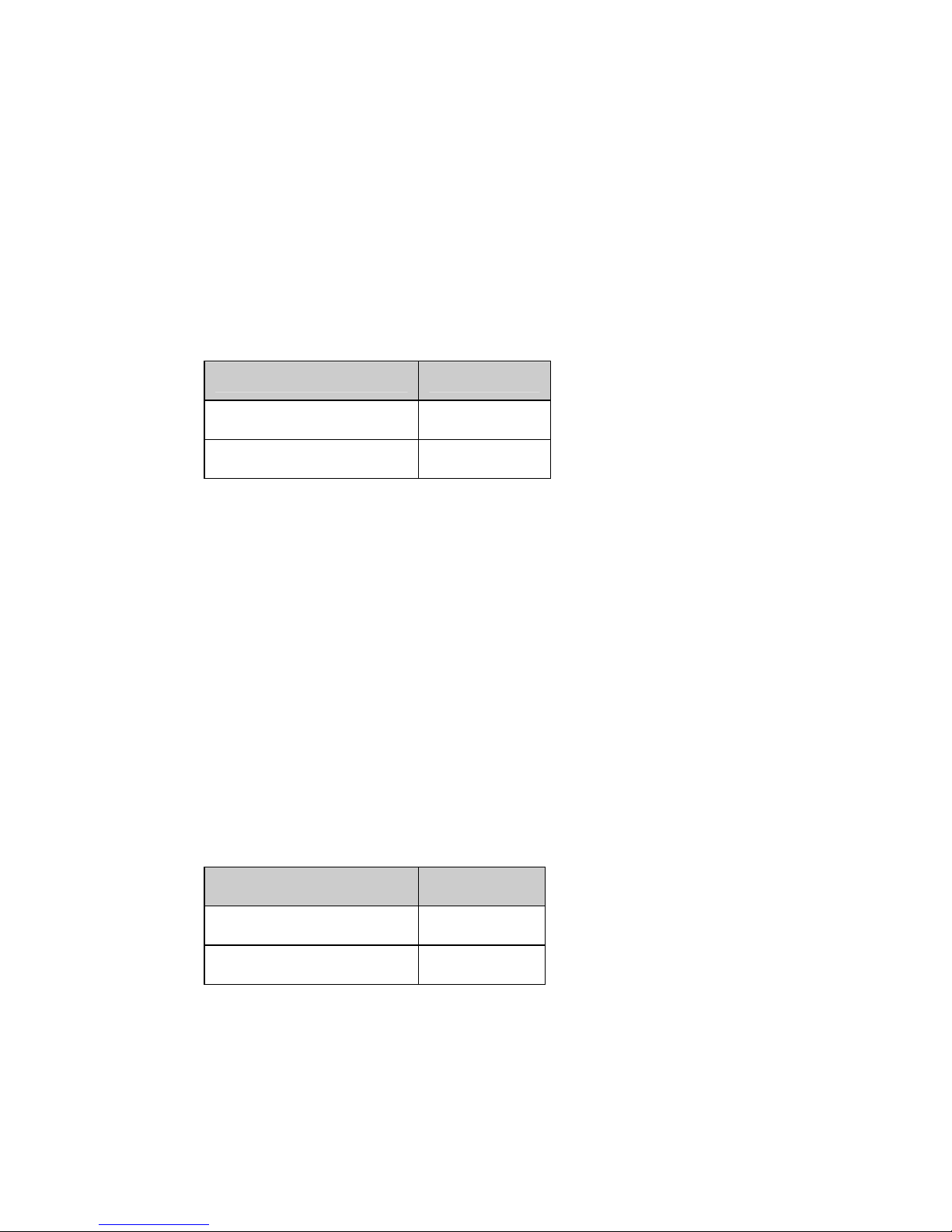
Dip Switches
The Dip switches are accessible through the opening in the side
of the enclosure.
NOTE: All switch changes take effect immediately and will
result in a link reset on both the Line and the Ethernet
port(s).
Dip Switch Settings
Auto Local (CO) / Remote (CPE) (Switch 1)
Switch Position Mode
On (Default) Auto Local
Off Remote
NOTE: Ethernet Extenders work in pairs. One side of the link
must be set to Local / CO and the other end of the link must
be set to Remote / CPE.
Perle 10/100/1000 Ethernet Extenders
5
Auto Local: This Ethernet extender is set to Auto Local mode of
operation. If both units are set to Auto Local, the Auto Connect
feature will be activated and the two units will automatically
determine their role (Local or Remote) and establish a
connection. It is preferable to set (via this Dip switch) one unit to
Auto Local and one unit to Remote since this may result in
slightly faster training times and direct control over their roles.
Remote: This Ethernet Extender is set to Remote mode of
operation.
Rate/Reach (Speed) (Switch 2)
Switch Position Mode
Up (default) High Speed
Down Long-Range
High Speed: In this mode, the VDSL connection will be
optimized for speed and the effective bidirectional data rate will
be up to 100 mbps in each direction. This setting also enables
VDSL Fast Mode.
Long Range: In this mode, the VDSL connection will be
optimized for distance and the achievable distance will be up to 3
km.
NOTE:
The actual distance and rates may vary depending
on the environment and type/gauge of wire used. There will
always be a compromise betweens speed and range.
For information on hardware specifications, range and reach see
the Perle website at www.perle.com.
Symmetric/Asymmetric (Switch 3)
Switch Position Mode
Up (default) Symmetric
Down Asymmetric
Symmetric: Set this switch to Symmetric if your network data
needs are almost equal for uploads and downloads (both
directions).
Perle 10/100/1000 Ethernet Extenders
6
Asymmetric: Set this switch to Asymmetric if your network data
needs are primarily for downloads. (Data direction is towards the
remote Ethernet Extender).
Signal to Noise Ratio (Switch 4)
Switch Position Mode
Up (default) 9dB
Down 6dB
This switch is used to configure the Signal to Noise Ratio Margin
(SNR). The Ethernet Extender will attempt to maintain the
desired SNR value by adjusting line settings. A larger dB number
will result in less line errors and a more stable connection, but
may result in slower speeds.
Signal to noise ratio 9dB: This setting is recommended if Rate
(switch 2) has been set to High Speed.
Signal to noise ratio 6dB: This setting is recommended if Rate
(Switch 2) has been set to Long Range.
Line Loopback (Switch 5)
Switch Position Mode
Up (default) Loopback
mode off
Down Loopback
mode on
Line Loopback Mode off: The Line loopback feature is off. This
is default position for normal operation. The switch must be set to
this position in order for data to pass through the Ethernet
Extender.
Line Loopback Mode on: This is a test mode. All data received
on the Line connection is internally looped back and
retransmitted back over the Line. This mode will override
Ethernet and Link Mode switch settings.
Ethernet Auto Negotiation (AutoNeg) (Switch 6)
Switch Position Mode
Up (default) AutoNeg On
Perle 10/100/1000 Ethernet Extenders
7
Down AutoNeg Off
NOTE: AutoNeg should only be turned off if fixed settings
are required by the Ethernet copper link partner.
Ethernet AutoNeg On: When enabled, the Ethernet Extender
will negotiate with its link partner to determine the most optimal
parameters for the Ethernet connection(s). The Ethernet
Extender will advertise capabilities of 10,100 (for eX-S110
models) and 10,100,1000 Mbps (for eX-S1110 models), full and
half duplex as well as pause, and remote fault capabilities to the
link partner.
Ethernet AutoNeg Off: When the Auto Negotiation switch is set
to the OFF position, the Ethernet Extender will not negotiate the
Ethernet parameters with the Ethernet link partner. The
parameters used by the Ethernet Extender Module will be
determined by the Ethernet Speed (Switch 7) and Ethernet
Duplex (Switch 8) Dip switch settings.
Ethernet Speed (Switch 7)
Switch Position Mode
Up (default) 100 Mb
Down 10 Mb
Ethernet Speed Up: 100 Mb for all models
Ethernet Speed Down: 10 Mb for all models
Note: When AutoNeg (SW6) is set to Off, the Ethernet
Extender will use this Speed setting for its Ethernet
connection.
Ethernet Duplex (Switch 8)
Switch Position Mode
Up (default) Full Duplex
Down Half Duplex
Note: When AutoNeg (SW6) is set to Off, the Ethernet
Extender will use this Duplex setting for its Ethernet
connection(s).

Perle 10/100/1000 Ethernet Extenders
8
Ethernet Duplex Up: Full Duplex mode.
Ethernet Duplex Down: Half Duplex mode.
Perle 10/100/1000 Ethernet Extenders
9
Link Mode (Switch 9) (1 port models)
Switch Position Mode
Up (default) Standard Mode
Down Link Pass-through
Standard Mode: In this mode, the Ethernet Extender will not
pass the state of the Ethernet interface across the Line
connection to its peer. A loss on the Ethernet interface can occur
without affecting the peer connection.
Link Pass-Through: In this mode, the Ethernet Extender will
pass the state of the Ethernet interface across the Line
connection to its peer. If link is lost on the Ethernet connection,
then the peer Ethernet connection will be brought down by the
remote Ethernet Extender. This is accomplished by signalling
Link Pass-Through across the VDSL line without bringing down
the link.
NOTE: Link Pass-Through will need to be enabled on both
the Local and Remote Ethernet Extender.
Link Pass-Through
If the Ethernet link is broken, its state is reflected on the peer’s
Ethernet link.
Interlink Fault Feedback (Switch 10) (1 port models)
Switch Position Mode
Up (default) Standard Mode
Down Interlink Fault Feedback
Perle 10/100/1000 Ethernet Extenders
10
Standard Mode: The status of the VDSL interface will not be
passed to its Ethernet interface
Interlink Fault Feedback: The status of the VDSL interface will
be passed to its Ethernet interface. If the VDSL line link is lost
the Ethernet link will be brought down.
Interlink Fault Feedback
The 10/100/1000 ports (LNK) on each of the links will be turned
off if the VDSL link is broken.
Connecting to the Ethernet Port
1.
Locate 1 Gigabit or 10/100Base-T compliant copper cables
with male, RJ-45 connectors installed at both ends.
2.
Connect the RJ-45 cable directly to the RJ-45 port labelled
ETH on the front of the Ethernet Extender. The other end of
this cable can be connected directly to a hub, switch or PC
using a straight through or crossover cable that is less than
328ft in length.
NOTE: The Perle Ethernet Extender supports Auto-MDIX
which allows the use of a straight-through or cross-over
Ethernet cable.
Questo manuale è adatto per i seguenti modelli
35
Indice
Altri manuali Perle Estensione


