
Perma Pure Baldwin series Manuale utente

Perma Pure LLC • A Halma Company • info@permapure.com • www.permapure.com
Telephone: 732-244-0010 • Toll Free: 800-337-3762 • Fax: 732-244-8140
1001 New Hampshire Ave., Lakewood, NJ 08701 USA
Baldwin™-Series
Model 5210D
Thermo-Electric Cooler
User’s Manual

Model 5210D User’s Manual
Doc. SE-MAN-050 REV 00
Page 2 of 25
©2017 Perma Pure LLC. All rights reserved. Specifications subject to change.
CONTENTS
3. Introduction
6. Specifications
6. Connections
7. Important Safety Warnings
8. Installation
8. Hardware required for installation
8. Mounting
8. Connections
8. Sample and Drain
9. Board Connections
13. LED Summary
14. Start-up
15. Troubleshooting and Maintenance Guide
19. Replacement Parts
20. Appendix A: Cooler Drawings
20. A1: Model 5210D dimensional drawing
21. A2: Impinger diagram
22. Appendix B: Sample Conditioning System Drawings
22. B1: Flow schematic
23. Appendix C: Conversion Table
25. Appendix D: Warranty and Disclaimer

Model 5210D User’s Manual
Doc. SE-MAN-050 REV 00
Page 3 of 25
©2017 Perma Pure LLC. All rights reserved. Specifications subject to change.
UNPACKING
Perma Pure has made every effort to ship you a high-quality product that has been thoroughly inspected and
tested. It has been carefully packed to ensure that it arrives at your facility in good condition. Even though every
effort has been made to prevent damage during the transportation process, damage can occur by the carrier. This
is out of control of Perma Pure and is the responsibility of the carrier to ensure that your equipment arrives intact
and undamaged.
Inspect outside packaging. If there is any visible damage, inform the carrier at the time of deliver. This
inspection is important! Once the package is signed for, responsibility for any visible damage then
transfers to the consignee.
Unpack your equipment. Visually inspect the outside of your equipment for any damage. If there is any
damage, contact the carrier immediately. Generally, a carrier must be notified within 24 hours of the delivery
to make a hidden damage claim.
Items in the carton include:
(1) Model 5210D thermo-electric cooler
(1) User’s Manual
Optional glass impingers will ship separately.
If any of the above parts are missing or damaged, call the helpline at (800) 337-3762.
INTRODUCTION
Thank you for purchasing this product from Perma Pure LLC. This manual has been assembled so that it can
answer all questions regarding operation. Please keep the operators manual near the equipment for future
reference. There may also be optional equipment available that was not ordered at the time of original purchase,
which may be described and/or illustrated in this manual.
If you still have any questions regarding your equipment’s operation, available options or technical support,
please contact your purchasing dealer or contact Perma Pure directly.
Perma Pure LLC Tel: 732-244-0010
1001 New Hampshire Ave. Tel: 800-337-3762 (toll free US)
Lakewood, NJ 08701 Fax: 732-244-8140
website: www.permapure.com e-mail: [email protected]
This equipment is to be installed and operated by trained personnel, with sufficient command of the English
language to clearly understand the instructions and safety warnings.
Model 5210D User’s Manual
Doc. SE-MAN-050 REV 00
Page 4 of 25
©2017 Perma Pure LLC. All rights reserved. Specifications subject to change.
PRINCIPLE OF OPERATION
One of the natural products of combustion (and
other processes) is significant amounts of water
in the form of vapor. Most measurement
processes require this water to be removed for
proper measurement and/or reliability of the
system. The cooler rapidly lowers the
temperature of the sample stream in the impinger
to just above the freezing point of the water,
thereby forcing water vapor to condense. Once
condensed, it is collected and removed. The
5210D is a thermoelectric cooler, which utilizes
TECs (also called Peltier elements) to provide
active cooling. The cooler may include a passive
stage, where the cold block is thermally mated
directly to the heat sink. The Peltier element is a
key element to this type of cooler. When
powered, one side becomes cold and the other
side becomes hot. The control system monitors
the coldest point on the heat transfer block, and
holds it to just above freezing, preventing the sample
stream from icing up. The control system reacts to
variations in temperature at the heat transfer block, maintaining the set point as the load or ambient conditions
vary.
LIMITATIONS:
There are limitations to what a thermoelectric cooler can do. The Peltier elements can only move so much heat. If
more heat is applied to the channel than the element can move for a given set point, the element will be
overwhelmed and the temperature will rise above the set point. The Peltier element generates a differential
temperature for a given voltage and load. As the ambient temperature rises, the hot side heat sink rises with it.
Should ambient conditions become too hot the element will no longer be able to maintain the set point for the
applied load. Ambient conditions should be within specifications for proper operational characteristics. As
mentioned above, a cooler lowers the temperature of the sample stream to just above freezing. This process may
drop out other constituents of the sample stream with the water, some which may impact your measurements.
Perma Pure Provides Nafion-based sample conditioning systems which prevent loss of water soluble analyses
using a permeation method for sample drying.
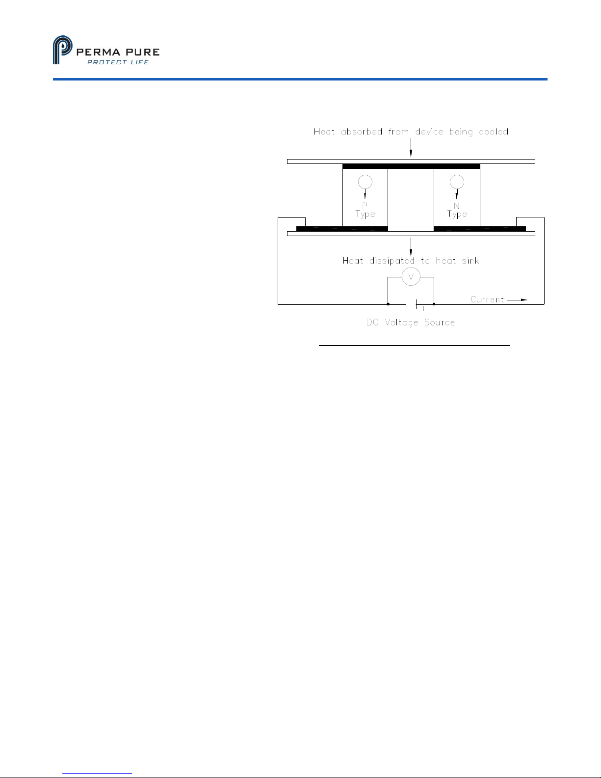
Figure 1: Thermo-electric element (Peltier)
Model 5210D User’s Manual
Doc. SE-MAN-050 REV 00
Page 5 of 25
©2017 Perma Pure LLC. All rights reserved. Specifications subject to change.
KEY COMPONENTS OF A THERMO-ELECTRIC COOLER:
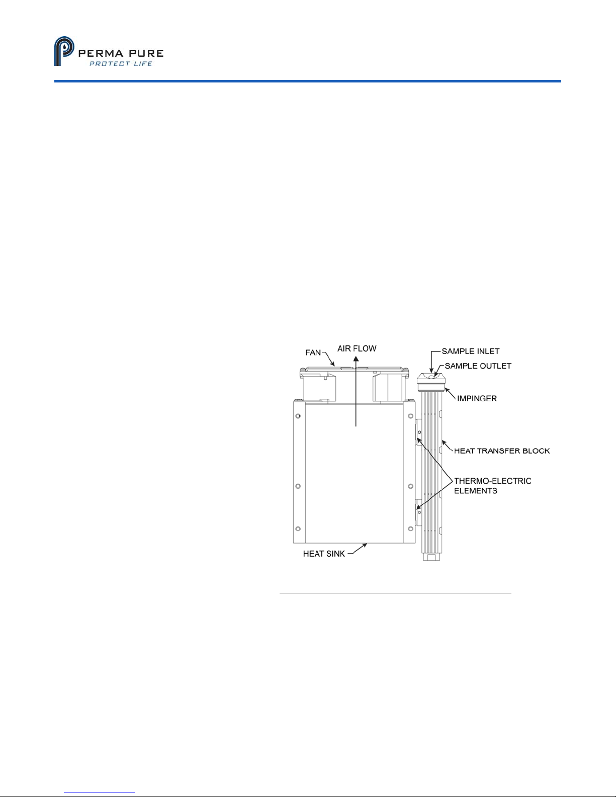
1) Peltier Element: When DC voltage is applied to the Peltier element, one side of the element becomes
cold, and the other hot. This heating and cooling effect at the junction of dissimilar metals is referred to as
the Peltier effect, named after the physicist who discovered it in 1834. The Peltier elements used here are
very powerful, and if not properly mated to a thermal sink will get extremely hot very quickly. DO NOT
POWER these elements without proper connection to a heat sink! You may get burned, and will damage
or destroy the element!
2) Heat Sink: The Peltier elements generate a significant amount of waste heat when in operation. This
heat is conducted into a heat sink to be removed into the ambient environment by forced convection.
3) Heat Sink Fan: The above mentioned forced convection.
4) Heat Transfer Block: This is the mechanical and thermal interface between the cold side of the Peltier
elements and the walls of the impinger. The heat transfer block provides a conductive path and
mechanical interface between the long cylindrical impinger and the rectangular Peltier elements.
5) Impinger: Interface between the sample stream and the heat transfer block. Water vapor condenses
along the outer wall and collects in the bottom for extraction. The sample stream travels through the
impinger, so corrosion resistance must be considered.
6)
Power Supply: AC to regulated DC to provide sufficient amperage for the Peltier elements configuration.
Peltier elements have a very specific
power to performance curve.
Performance can be adversely
affected by supplying too much
power. The power supply provided is
factory adjusted, and should not be
altered!
7) Control Thermistors: Measures
temperature of the heat transfer
block at the Peltier element interface
for feedback to control electronics.
This is the temperature displayed,
and is the coldest point on the heat
transfer block.
8) Control Electronics: Regulates
power supplied to Peltier elements to
maintain a set temperature. The
control electronics provides Pulse
Width Modulated (PWM) power to
the Peltier elements, regulated by a
control loop.
9) Peristaltic Pump (not covered
here): Removes condensate from
the impinger without creating a path
for outside air to enter the sample stream.
Figure 2: Heat Exchanger, Impinger and Heat Sink

Model 5210D User’s Manual
Doc. SE-MAN-050 REV 00
Page 6 of 25
©2017 Perma Pure LLC. All rights reserved. Specifications subject to change.
PHYSICAL DESCRIPTION
Single (Series) or Dual (Parallel) stream system
1 x 10” heat exchanger connected in series; actively cooled to the temperature set point
1 x 10” heat exchanger connected in series; passively cooled by direct contact with the heat sink
LCD temperature display
Dimensions: 14.5” x 11” x 10.5” HWD (37 x 28 x 26.5 cm)
Weight: 35 lbs (16 kg)
SPECIFICATIONS
Sample gas flow range Up to 8 LPM (Up to 17 SCFH)
Avg. inlet dew point at rated flow 20% H2O (60°C DP) @ 5 LPM
Maximum cooling rate 440 BTU/hr (464 kJ/hr)
Maximum inlet sample temp. 400°F (205°C) for SS or glass impingers
280°F (138°C) for Kynar™ impingers
Maximum inlet pressure 15 psig (1 bar;760 mmHg)
Maximum pressure drop <+1 in H2O
Ambient temperature range 33-104°F (0.6-40°C)
Outlet sample gas dew point 39°F (4°C)
Voltage 115 OR 230 VAC (Verify before energizing
equipment) 50/60 Hz
Power supply 600 Watt
Cooling down time Less than 6 minutes
CONNECTIONS
Sample gas inlet: Kynar, 3/8” tube compression fitting
Sample gas outlet: Kynar, 1/4” tube compression fitting
Drain tubing connection: Kynar, ¼” barbed tube fitting
An automatic condensate drain, dual-head peristaltic drain pump is recommended (not included) for
water removal, Perma Pure part number 3KPB-003; size 17 tubing.
Always use factory supplied fittings; Perma Pure cannot warrant against damage to the Peltier elements or heat
exchangers if our fittings are not used.

Model 5210D User’s Manual
Doc. SE-MAN-050 REV 00
Page 7 of 25
©2017 Perma Pure LLC. All rights reserved. Specifications subject to change.
IMPORTANT SAFETY WARNINGS
Please be sure to review the following basic safety procedures. These procedures represent the MINIMUM
requirements to operate the equipment safely. It is the ultimate responsibility of the operator to ensure
that proper safety practices are utilized at the point of operation.
NEVER attempt to operate this equipment in an explosive or otherwise hazardous area.
NEVER exceed any specified rating for the equipment. Voltage, temperature and pressure ratings must be
closely observed and not exceeded. Voltage rating of the equipment MUST match the rating on the data
label. Please make sure that it matches before powering up the equipment.
This equipment is NOT designed to be used in an explosive environment.
This equipment is NOT designed to operate in a wet environment.
Condensate is potentially dangerous. NEVER handle drain lines, impingers or any other item that may
have come into contact with the gas stream or any hazardous material, without adequate personal protective
equipment. ALWAYS assume that any liquid present is hazardous.
Sample gas is potentially dangerous. A leak test is recommended at initial startup and as often as
necessary to maintain a safe working environment around the equipment. The gas stream exhaust must exit
away from all personnel to prevent dangerous exposure.
NEVER operate the equipment with any part of the enclosure unsecured. All operating doors and
covers must be in place and secured prior to operation. Electrical current may be present behind covers or
doors, even if tools are not necessary to access these components.
NEVER attempt service on this equipment without first disconnecting all energy sources. Repair of this
equipment should only be done by properly trained personnel that are familiar with the potential risks
involved with servicing of the equipment.
NEVER replace fuses with types other than the sample specification of type and current. Do not bypass this
or any other safety device.
NEVER operate this equipment if it is visibly damaged or the possibility exists that it may have been
damaged.
The use of components that have not been purchased through an authorized Perma Pure dealer or directly
from Perma Pure may compromise the safety of the operator. Additionally, use of non-authorized
components may change the operating characteristics of this equipment. Any changes to the equipment, that
modify its operation in any way, are dangerous, and are strictly prohibited.
Read the entire operating manual before attempting to set up or operate the equipment.
Please heed all warning labels that are on the equipment. They are there to remind you of possible
hazardous conditions.
Verify the integrity of any mechanical and/or electrical connections that are made to the unit.
Verify that the unit is connected to the proper rated power for the system
Verify that the unit is plumbed properly to operate effectively

Model 5210D User’s Manual
Doc. SE-MAN-050 REV 00
Page 8 of 25
©2017 Perma Pure LLC. All rights reserved. Specifications subject to change.
INSTALLATION
Hardware required for installation
(4) ¼-20 mounting screws
For stainless steel sample lines, 2 inches of 3/8” Teflon tube
Peristaltic drain pump, dual head
Mounting
The Classic Model 5210D Thermo-Electric Cooler should be installed away from heat sources in a well
vented area.
NOTE: The operational stability of the cooler dew point is influenced by the stability of the
ambient temperature.
For proper operation, the ambient temperature cannot exceed 40°C (104°F). At, or close to the maximum
ambient temperature, the cooler will not be able to control the temperature to reduce the dew point of the
sample gas to the 4°C set point. This will result in compromised operation and water slip or carryover,
possibly into the analyzer. Also, at or near this temperature, the cooler will be running “full on” and Peltier
life will be greatly reduced.
CONNECTIONS
Sample and Drain
1. Connect the sample inlet to the 3/8” tube fitting shown in figure 3 below.
NOTE: If using heated stainless steel sample line, add 2 inches of Teflon tubing at the heat exchanger
inlet fitting, and connecting it to the heated line. This isolates the heated line from the heat exchanger
and prevents excessive heating of the heat exchanger, possibly overloading the cooler.
2. Connect the sample outlet to the 1/4” tube fitting shown in the figure.
3. Connect the peristaltic pumps to the ¼” barbed tube fittings at the base of the impinger.
NOTE: Do not reduce the size of the condensate tubing since doing so restricts water flow resulting in
water carryover into the sample.
Figure 3: Model 5210D Cooler
Model 5210D User’s Manual
Doc. SE-MAN-050 REV 00
Page 9 of 25
©2017 Perma Pure LLC. All rights reserved. Specifications subject to change.
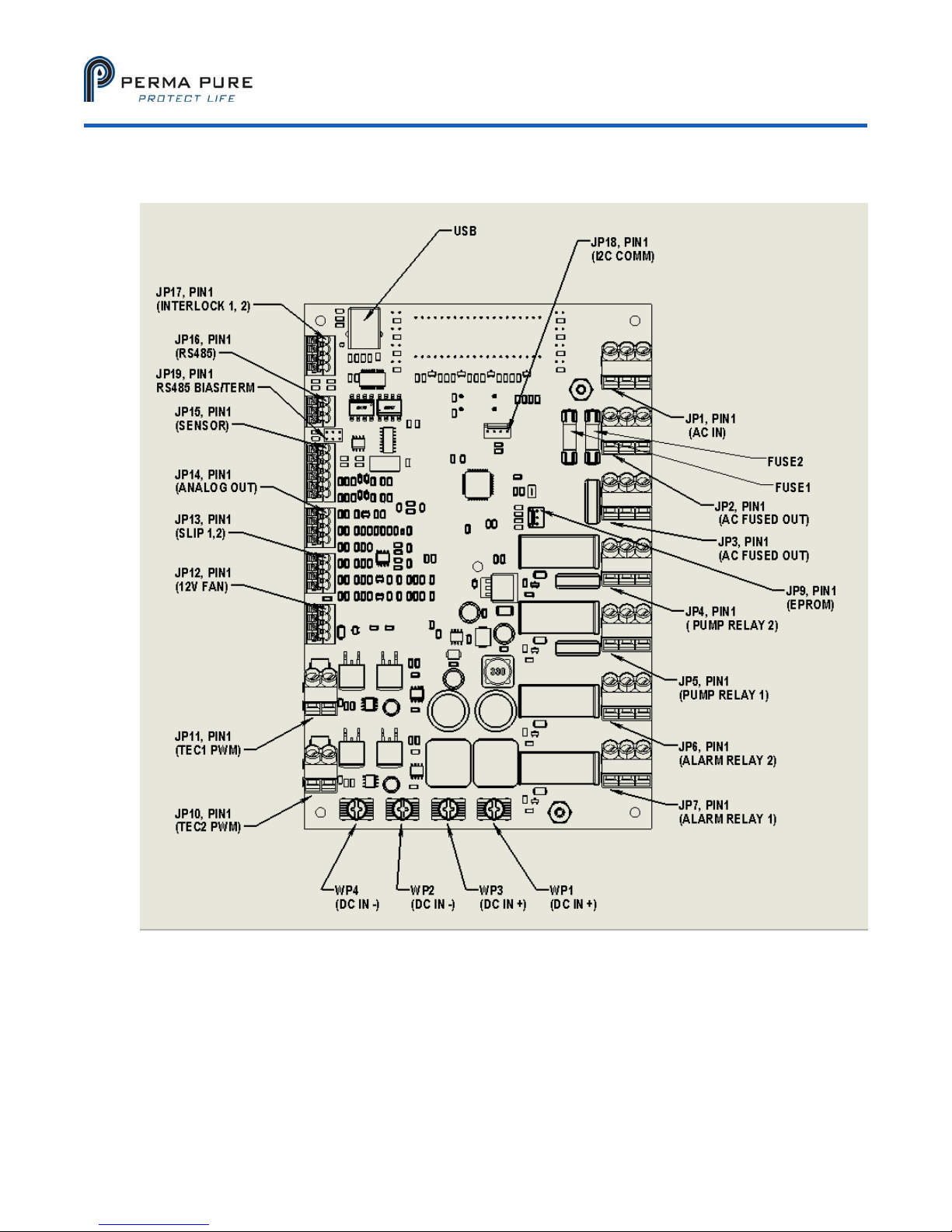
BOARD CONNECTIONS
Model 5210D User’s Manual
Doc. SE-MAN-050 REV 00
Page 10 of 25
©2017 Perma Pure LLC. All rights reserved. Specifications subject to change.
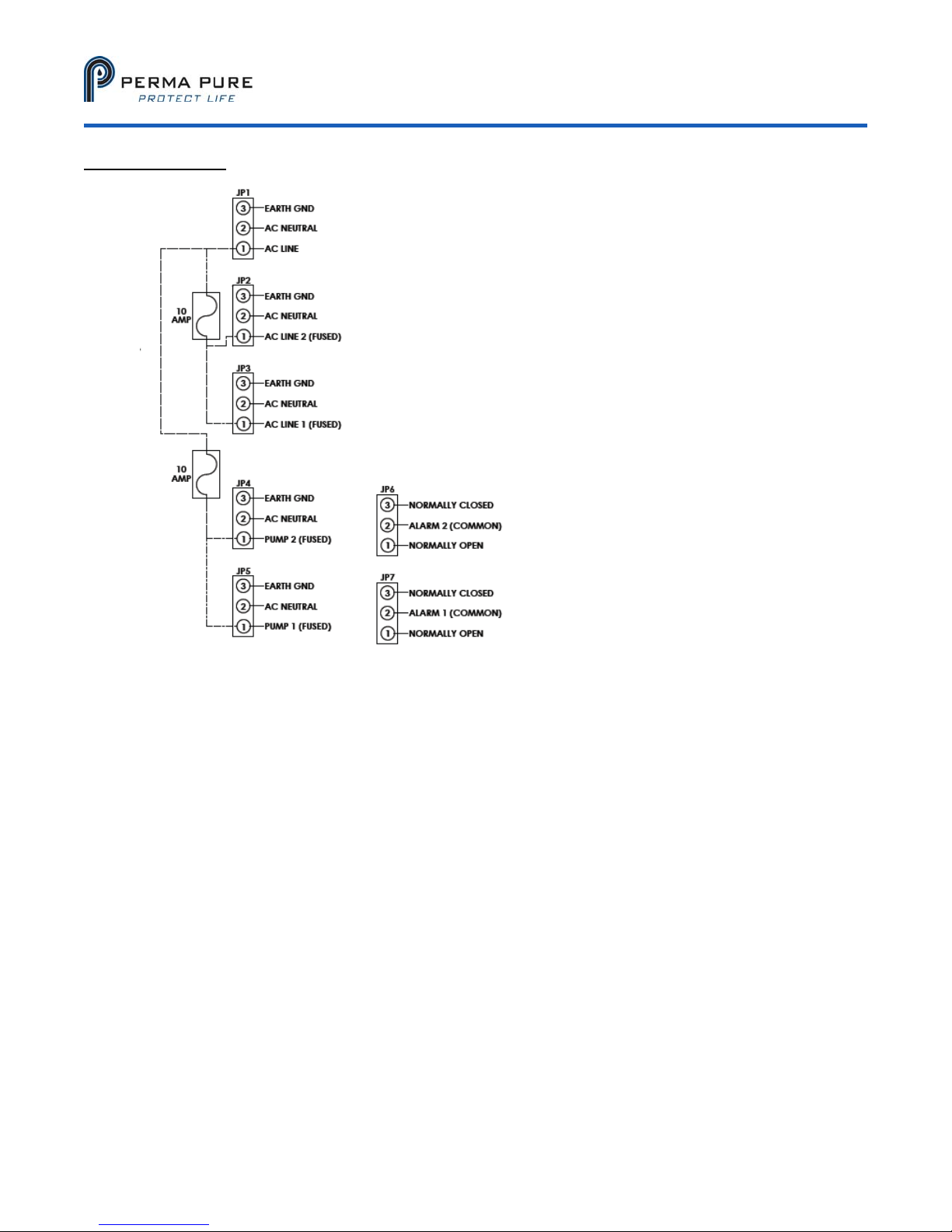
AC side (right side)
JP1: AC line in for accessory control.
JP2: Fused power out from JP1, currently heatsink fan.
JP3: Fused power out from JP1
JP4: Fused pump relay for Channel 2. Relay applies power to circuit when temperature is
below “ready” temperature. Circuit will open when temperature is above the ready
temperature. This avoids passing vapor exceeding the “ready temperature” dew point.
JP4 and JP5 operate independently of each other.
JP5: Fused pump relay for Channel 1. Relay applies power to the circuit when temperature is
below “ready” temperature. Circuit will open when temperature is above the ready
temperature. This avoids passing vapor exceeding the “ready temperature” dew point.
JP4 and JP5 operate independently of each other.
JP6-L Channel 2 alarm relay. Isolated relay which can be wired Normally Open (N.O.) or
Normally Closed (N.C.). JP6 and JP7 operate independently of each other. A sensor
failure (short or open) will trip the relay.
JP7: Channel 1 alarm relay. Isolated relay which can be wired NC or NO (normally open or
normally closed). JP6 and JP7 operate independently of each other. NOTE: The board is
incorrectly physically labeled.
FUSE1: 10Amp fuse between JP1 and JP2 and JP3
FUSE2: 10 Amp fuse between JP1 and JP4 and JP5 (pump relay controlled)
Altri manuali per Baldwin series
3
Questo manuale è adatto per i seguenti modelli
1
Indice
Altri manuali Perma Pure Accessori


