Phantom Cables CA-AC346-FDF-2WH Manuale utente

Analog Color Night Vision Camera
CA-AC346-FDF-2WH
User Manual

2
Contents
User Manual ...........................................................
Regulatory Information .....................................................
FCC Information ...........................................................
FCC Compliance ...........................................................
FCC Conditions ...........................................................
EU Conformity Statement ..................................................
Industry Canada ICES-00 Compliance ............................ 4
Warning ........................................................... 4
Safety Instruction ........................................................... 4
Warnings ........................................................... 4
Cautions ........................................................... 5
Mark Description ........................................................... 5
1 Introduction ........................................................... 6
1.1 Product Features ................................................... 6
1.2 Overview ................................................................. 6
1.2.1 Overview of Type I Camera ..................................... 6
1.2.2 Overview of Type II Camera .................................... 6
1.2. Overview of Type III Camera.................................... 6
2 Installation ............................................................. 7
2.1 Installation of Type I Camera ................................. 7
2.1.1 Ceiling/Wall Mounting without Junction Box ........ 7
2.1.2 Ceiling/Wall Mounting with Junction Box ............. 8
2.2 Installation of Type II Camera ................................ 9
2.2.1 Ceiling/Wall Mounting without Junction Box ........ 9
2. Installation of Type III Camera.............................. 11
2. .1 Ceiling/Wall Mounting without Junction Box ...... 11
2.4 Ceiling/Wall Mounting with Junction Box ........... 12
Menu Description ................................................. 14
.1 VIDEO FORMAT ....................................................... 16
.2 EXPOSURE .............................................................. 16
.2.1 EXPOSURE MODE .................................................... 16
.2.2 AGC (Auto Gain Control) ........................................ 16
.2. SLOW SHUTTER ...................................................... 16
.2.4 ANTI-BANDING ....................................................... 16
. VIDEO SETTINGS ..................................................... 17
. .1 IMAGE MODE ......................................................... 17
. .2 WHITE BALANCE..................................................... 17
. . BRIGHTNESS ......................................................... 17
. .4 CONTRAST ......................................................... 17
. .5 SHARPNESS ......................................................... 17
. .6 SATURATION ......................................................... 18
. .7 DNR ( D DNR) ...................................................... 18
. .8 MIRROR ......................................................... 18
.4 SMART LIGHT ......................................................... 18
.5 FUNCTIONS ............................................................. 18
.5.1 MOTION DET ......................................................... 18
.5.2 PRIVACY ......................................................... 18
.6 FACTORY DEFAULT ................................................. 18
.7 EXIT ................................................................... 19
.8 SAVE & EXIT ........................................................... 19

User Manual
Thank you for purchasing our product. If there are any
questions or requests, please contact your dealer.
This manual applies to the models below:
This manual may contain technical mistakes or printing
errors, and the content is subject to change without
notice. Updates will be added to new versions of this
manual. We will readily improve or update the products
or procedures described in the manual.
Regulatory Information
FCC Information
Please take attention that changes or modification not
expressly approved by the party responsible for
compliance could void the user’s authority to operate
the equipment.
FCC Compliance
This equipment has been tested and found to comply
with the limits for a Class A digital device, pursuant to
part 15 of the FCC Rules. These limits are designed to
provide reasonable protection against harmful
interference when the equipment is operated in a
commercial environment. This equipment generates,
uses, and can radiate radio frequency energy and, if not
installed and used in accordance with the instruction
manual, may cause harmful interference to radio
communications. Operation of this equipment in a
residential area is likely to cause harmful interference,
in which case the user will be required to correct the
interference at his own expense.
FCC Conditions
This device complies with part 15 of the FCC Rules.
Operation is subject to the following two conditions:
This device may not cause harmful interference.
This device must accept any interference received,
including interference that may cause undesired
operation.
EU Conformity Statement
This product and, if applicable, the supplied
accessories too are marked with “CE” and
comply therefore with the applicable
harmonized European standards listed under the Low
4
Voltage Directive 2014/ 5/EU, the EMC Directive
2014/ 0/EU,
the RoHS Directive 2011/65/EU
.
2 12/19/EU (WEEE Directive): Products marked
with this symbol cannot be disposed of as
unsorted municipal waste in the European
Union. For proper recycling, return this product
to your local supplier upon the purchase of
equivalent new equipment, or dispose of it at
designated collection points. For more information see:
www.recyclethis.info.
2 6/66/EC (Battery Directive): This product
contains a battery that cannot be disposed of
as unsorted municipal waste in the European
Union. See the product documentation for specific
battery information. The battery is marked with this
symbol, which may include lettering to indicate
cadmium (Cd), lead (Pb), or mercury (Hg). For proper
recycling, return the battery to your supplier or to a
designated collection point. For more information, see:
www.recyclethis.info.
Industry Canada ICES- 3 Compliance
This device meets the CAN ICES- (A)/NMB- (A)
standards requirements.
Warning
This is a class A product. In a domestic environment this
product may cause radio interference, in which case the
user may be required to take adequate measures.
Safety Instruction
These instructions are intended to ensure that the user
can use the product correctly to avoid danger or
property loss.
The precaution measures are divided into “Warnings”
and “Cautions.”
Warnings: Serious injury or death may occur if any of the
warnings are neglected.
Cautions: Injury or equipment damage may occur if any
of the cautions are neglected.
Warnings
Follow
these
safeguards to prevent
serious injury or death.
Cautions
Follow these
precautions to prevent
potential injury or material
damage.
Warnings
In the use of the device, you must be in strict
compliance with the electrical safety regulations of the
nation and region.

5
Input voltage should meet both the SELV (Safety Extra
Low Voltage) and the Limited Power Source with 12 VDC
according to the IEC60950-1 standard. Refer to
technical specifications for detailed information.
Do not connect multiple devices to one power adapter
to avoid overheating or a fire hazard caused by overload.
Make sure that the plug is firmly connected to the power
socket.
Make sure that the device is firmly fixed if wall mounting
or ceiling mounting is used.
If smoke, odor, or noise rise from the device, turn off the
power at once, unplug the power cord, and contact the
service center.
Untrained personnel should never attempt to
disassemble the camera.
Cautions
Do not drop the camera or subject it to physical shock.
Do not touch sensor modules with fingers.
Do not place the camera in extremely hot, cold (the
operating temperature shall be -40° to 60° C), dusty, or
damp locations, and do not expose it to high
electromagnetic radiation.
If cleaning is necessary, use a clean cloth with a bit of
ethanol, and wipe it gently.
Do not aim the camera at the sun or extra bright places.
The sensor may burn out by a laser beam, so if any laser
equipment is in use, make sure that the surface of the
sensor will not be exposed to the laser beam.
Do not expose the device to high electromagnetic
radiation or an extremely hot, cold, dusty, or damp
environment.
To avoid heat accumulation, good ventilation is required
for the operating environment.
Keep the camera away from liquid while in use for non-
waterproof device.
While in delivery, the camera shall be packed in its
original, or similar, packing.
Mark Description
Table 0-1 Mark Description
Mark
Description
DC Voltage
6
1Introduction
1.1 Product Features
The main features are as follows:
•High performance CMOS sensor
•OSD menu with configurable parameters
•24-hour color image
•Smart light
•-axis adjustment
1.2 Overview
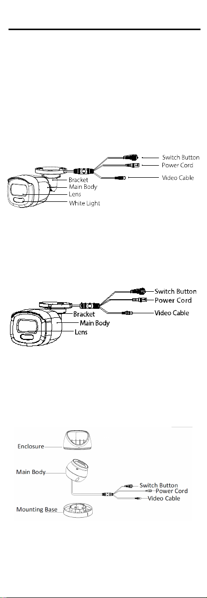
1.2.1 Overview of Type I Camera
Figure 1, Type 1 Camera Overview
NOTE: Press and hold the switch button for five
seconds to switch the video output. Four kinds
of video outputs are available: TVI, AHD, CVI, and
CVBS.
1.2.2 Overview of Type II Camera
Figure 2, Type II Camera Overview
NOTE: Press and hold the switch button for five
seconds to switch the video output. Four kinds
of video outputs are available: TVI, AHD, CVI, and
CVBS.
1.2.3 Overview of Type III Camera
Figure , Type III Camera Overview
NOTE: Press and hold the switch button for five
seconds to switch the video output. Four kinds
of video outputs are available: TVI, AHD, CVI, and
CVBS.
7
2Installation
Before You Start
•Make sure that the device in the package is in good
condition and all assembly parts are included.
•Make sure that all related equipment is powered off
during the installation.
•Check the products’ specifications for the installation
environment.
•Check whether the power supply matches your power
output to avoid damage.
•Make sure the wall is strong enough to withstand
three times the weight of the camera and the mount.
•If the wall is concrete, insert expansion bolts before
installing the camera. If the wall is wood, use self-
tapping screws to secure the camera.
•If the product does not function properly, contact
your dealer or the nearest service center. Do NOT
disassemble the camera for repair or maintenance
yourself.
2.1 Installation of Type I Camera
2.1.1 Ceiling/Wall Mounting without Junction Box
Before You Start
Ceiling mounting and wall mounting are similar. The
following uses ceiling mounting as an example.
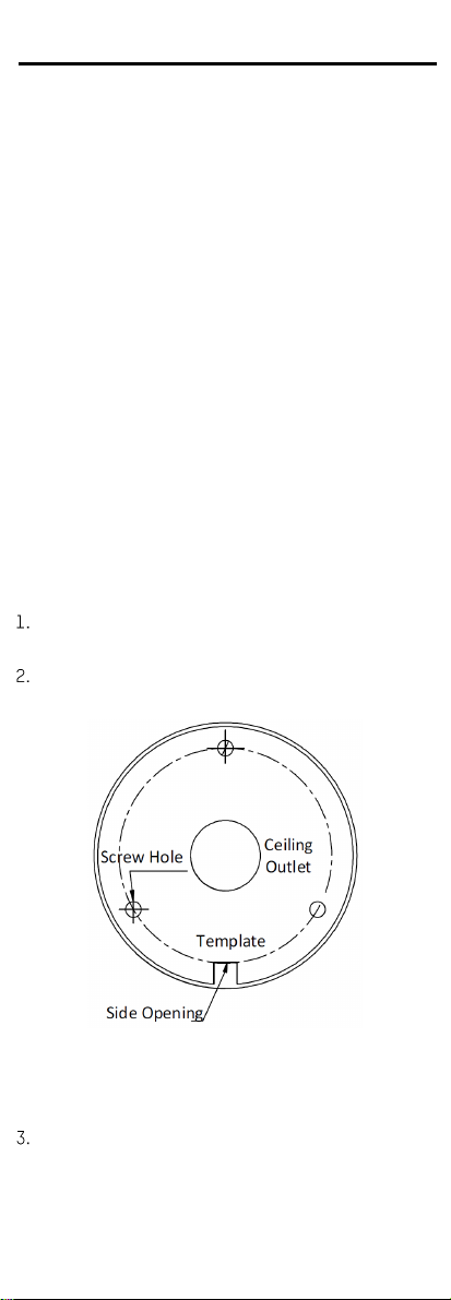
Paste the drill template (supplied) where you want to
install the camera.
Drill screw holes and the cable hole (optional) on the
ceiling according to the drill template.
Figure 4, Drill Template
NOTE: Drill a cable hole when using the ceiling outlet
to route the cable.
Route the cables through the cable hole or the side
opening.
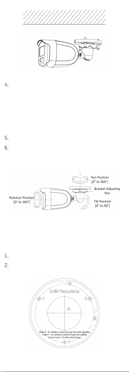
Figure 7, Drill Template of Junction Box
8
Figure 5, Secure the Camera to the Ceiling
Attach the bracket to the ceiling, and secure the
camera with supplied screws.
NOTES: The supplied screw package contains self-
tapping screws and expansion bolts.
For a concrete wall/ceiling, expansion bolts are
required to fix the camera. For a wood
wall/ceiling, self-tapping screws are required.
Connect the power cord and video cable.
Power on the camera to check if the image on the
monitor is at an optimum angle. If not, loosen the
bracket adjusting nut to modify the position.
Figure 6, -Axis Adjustment
2.1.2 Ceiling/Wall Mounting with Junction Box
Before You Start
You need to purchase a junction box in advance.
Paste the drill template (supplied) on the ceiling/wall.
Drill screw holes and the cable hole on the ceiling
according to the drill template.
install the camera.
9
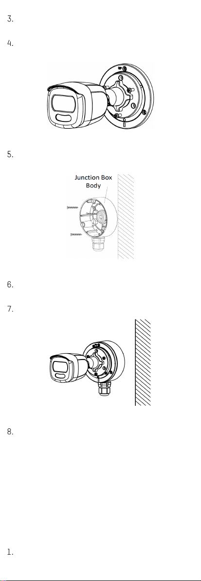
Take apart the junction box, and align the camera
screw holes with those on the junction box cover.
Attach the camera to the junction box cover with
supplied screws.
Figure 8, Attach Camera to Junction Box Cover
Secure the junction box body on the ceiling/wall with
supplied screws.
Figure 9, Secure Junction Box on Wall/Ceiling
Route the cables through the junction box’s bottom
cable hole or side cable hole.
Attach the junction box cover to its body.
Figure 10, Re-attach Junction Box Cover to its Body
Repeat steps 5 and 6 of
2.1.1 Ceiling/Wall Mounting
without Junction Box
to finish the installation.
2.2 Installation of Type II Camera
2.2.1 Ceiling/Wall Mounting without Junction Box
Before You Start
Ceiling mounting and wall mounting are similar. The
following uses ceiling mounting as an example.
NOTE: Installation with a junction box refers to
2.1.2
Ceiling/Wall Mounting with Junction Box.
Paste the drill template (supplied) where you want to
10
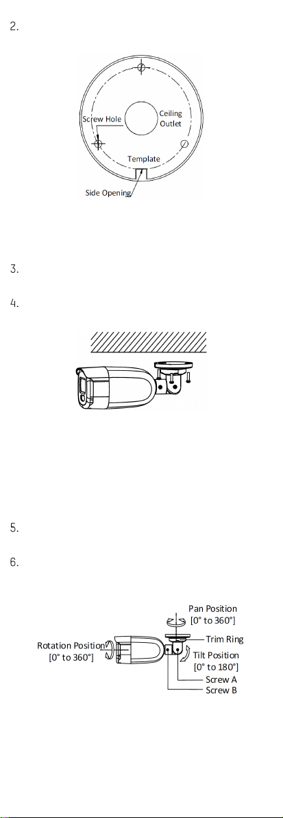
Drill the screw holes and the cable hole (optional) on
the ceiling according to the drill template.
Figure 11, Drill Template
NOTE: Drill a cable hole when using the ceiling outlet
to route the cable.
Route the cables through the cable hole or the side
opening.
Attach the bracket to the ceiling, and secure the
camera with supplied screws.
Figure 12, Secure the Camera to the Ceiling
NOTE: The supplied screw package contains self-
tapping screws and expansion bolts.
For a concrete wall/ceiling, expansion bolts are
required to fix the camera. For a wooden
wall/ceiling, self-tapping screws are required.
Connect the corresponding power cord and video
cable.
Power on the camera to check whether the image on
the monitor is at an optimum angle. If not, adjust the
camera according to the figure below.
Figure 1 , -Axis Adjustment
1) Loosen trim ring to adjust pan position [0° to 60°].
2) Loosen screw A to adjust tilt position [0° to 180°].
) Loosen screw B to adjust rotation position [0° to
60°].
Indice
Altri manuali Phantom Cables Telecamera di sicurezza

Phantom Cables
Phantom Cables CA-2440V-WH Manuale utente

Phantom Cables
Phantom Cables CA-2240V-WH Manuale utente

Phantom Cables
Phantom Cables CA-2480V-WH Manuale utente

Phantom Cables
Phantom Cables CA-2280V-WH Manuale utente

Phantom Cables
Phantom Cables CA-1120F2-GY Manuale utente

Phantom Cables
Phantom Cables CA-1120F2-WH Manuale utente

Phantom Cables
Phantom Cables CA-NC328P-VBZ-WH Manuale utente


