Phantom Viewpoint VI0508 Manuale utente

Installation Manual for
For Right and Left Hinged Doors
Durable. Reliable. Attractive.
For door openings up to 36” (914 mm) wide
and 80 9/16” (2,047 mm) high
Quick and
Easy to Size
and Install

Congratulations and
thank you for purchasing
Viewpoint!
The Viewpoint Screen is designed and manufactured by Seiki Screen
Systems, the world’s largest manufacturer of retractable screens.
Phantom Screens, North America’s leading brand of retractable
solutions, is proud to bring you these innovative products. Thanks to
rigorous design and product testing, the Viewpoint Screen will provide
years of dependable operation. Plus, it comes with a factory-supplied
limited lifetime warranty on all parts against manufacturer’s defects.
Viewpoint was designed for easy sizing and installation. This
Installation Manual provides a step by step guide through the
entire process.
Any questions? Contact
our Help Line, Toll Free at
1-877-446-7180.

Getting to Know the Viewpoint Screen ................
Parts and Tools ......................................................
Measuring the Door Opening ...............................
Cutting the Horizontal
and Vertical Parts ..................................................
Installing the Bottom Rail and
Preparing the Screen Housing Assembly ..............
Installing the Mounting Bracket ..........................
Installing the Top Rail
and Catch Frame .................................................
Adjusting the Latch
and Tension Wires ...............................................
Attaching the Fixing Strip
and Installing the Clips .......................................
Service and Maintenance Hints ..........................
Index
For installation on a double hinged door (French Doors), you
will need: two Viewpoint Screens and one Double Door Kit.
Please refer to the Installation Manual within the “Double
Door Kit” prior to starting.
The Viewpoint Screen is not intended for installation on a
Sliding Patio Door.
4
5
6
7
8
9
10
11
12
13

Getting to Know the Viewpoint Screen
Before beginning, become familiar with the
Viewpoint Screen and the door on which it
will be installed.
The Viewpoint Screen accommodates both
in-swing and out-swing doors. In-swing
doors open to the inside of the home and
require the Viewpoint Screen to be
installed on the outside of the home.
Out-swing doors open to the outside of the
home and require the Viewpoint Screen
to be installed on the inside of the home.
Does the Viewpoint Screen t the
Door Opening?
Make sure that the Viewpoint Screen
will t the door. This application
will accommodate an opening of
up to 36” (914 mm) wide, and between
76 9/16” (1,947 mm) and 80 9/16”
(2,047 mm) high. If the door opening is
larger than that, the Viewpoint Screen can
still be installed by attaching a ller strip
under the door frame to reduce the height of
the door opening. Refer to page 6 for details.
NOTE: The Viewpoint Screen can only be
shortened by 4” (100 mm) to a minimum
height of 76 9/16” (1,947 mm). If the door
opening is smaller than this, the Viewpoint
Screen will not accomodate the door.
4
Is the Door Opening Square?
For the Viewpoint Screen to operate
effectively, the door opening must be
perfectly square. Using a Carpenter
Square, check to ensure that the door
frame is square. If not, use shims to
bring the door frame to square before
beginning installation.
Is there enough Mounting Surface?
The Viewpoint Screen is a recess
mount screen that installs on the
inside surface of the door frame.
A minimum Mounting Surface of
1 3/4” (45 mm) is required. This
Mounting Surface must be at and
ush, and at a right angle (90˚)
to the door.
Door Frame
Corner Cover
Mesh
Mounting Bracket
Clip
Fixing Strip
Tension Wire
Bottom Rail
Sliding Bar Bottom Cap
Catch Frame
Latch Hole
Latch
Sliding Bar
Top Rail
Rollers
Mounting Surface Viewpoint Screen

Parts and Tools
Before beginning,
make sure that all these
parts are included with
the Viewpoint Screen
package.
Required Tools
Viewpoint Screens can be sized and installed using common household
tools. Make sure all necessary tools are available before beginning.
NOTE: A chop saw can be used in place of a hacksaw provided that a
bi-metal blade has been properly installed
5
Top Rail
Bottom Rail
Screen Housing
Assembly Catch Frame
(not required for a
double door application)
5/8” (16 mm)
Pan Head Screws
(12 pcs.)
1/2” (12 mm)
Flat Head Screws
(2 pcs.)
Door Frame
Corner Cover
Mesh
Mounting Bracket
Clip
Fixing Strip
Tension Wire
Bottom Rail
Sliding Bar Bottom Cap
Catch Frame
Latch Hole
Latch
Sliding Bar
Top Rail
Rollers
Hack saw Philips
screwdriver
Electric drillMeasuring tape LevelCarpenter
square
Pen
Corner Cover
Sliding Bar
Bottom Cap Clips (5 pcs.)

Measuring the Door Opening
H
W
The Viewpoint Screen requires a minimum
Mounting Surface of 1 3/4" (45 mm). This
mounting surface must be at and ush, and at
a right angle (90º) to the door.
For the Width - Measure the width of the
opening between the right and left surfaces of
the door frame, record this dimension in the box
below labeled “W”.
For the Height – Measure the height of the
opening between the underside of the top of
the door frame (or ller strip), and the top of
the door sill at a point 1 3/4" (45 mm) from the
front surface of the frame. Record this
dimension in the box below labeled “H”.
NOTE: If the height of the door opening is
greater than the maximum height requirement,
it is still possible to install the Viewpoint
Screen. Simply attach a ller strip under the
top of door frame to reduce the height of the
opening to at least 80 9/16" (2,047 mm). Be
sure to attach the ller strip before taking the
height measurement.
=
=
6
W
H
A
1 3/4”
(45 mm)
mounting
surface
Door Sill

-
Cutting the Horizontal and
Vertical Parts
Cutting the Horizontal Parts
Calculate the correct cut off Lengths.
Cut from each part the cut off length provided by the calculation performed above.
Maximum Opening
Width
Subtract inside door
frame width “W”
Enter Cut off Length
Below
36” (914 mm) =
After cutting any part of the
Viewpoint Screen, use a le
to remove any burrs from the
surfaces.
Cutting the Vertical Parts
Calculate the correct cut off Lengths.
NOTE: Cutting of the Screen Housing Assembly must take place from the
bottom of the unit, note the “Cut” / “No Cut” labels. No more than 4” (100 mm)
can be cut from the Screen Housing Assembly.
-
Maximum Opening
Height
Subtract inside door
frame height “H”
Enter Cut off Length
Below
80 9/16” (2,047 mm) =
Cut from each part the cut off length provided by the calculation performed above.
Do NOT remove the tape that keeps the components of the Screen Housing
Assembly secure until all cutting is complete. After cutting any part of the
Viewpoint Screen, use a le to
remove any burrs from the
surfaces.
NOTE: Safety glasses should
be worn at all times during the
cutting process.
7
Top Rail Bottom Rail
Cut O Length Cut O Length
Cut o Length
Screen Housing Assembly
Cut o Length
Catch Frame

Installing the Bottom Rail and
Preparing the Screen Housing Assembly
Remove the backing from the
double sided tape on the bottom
of the Bottom Rail. Attach the
Bottom Rail onto the door sill,
placing the front edge of the
Bottom Rail even with the face
or front edge of the door frame
on both sides of the opening.
Installing the Bottom Rail
Preparing the Screen Housing Assembly
1. Before installing the Screen
Housing Assembly,
rotate the Mounting Bracket so
that the Tension Wires are
no longer wound around it.
Failing to do so prior to
installing the Mounting Bracket
will restrict the motion of the
Tension Wires and prevent the
screen from operating.
2. Attach the Sliding Bar
Bottom Cap to the bottom of
the Sliding Bar using the two
screws provided.
3. Insert the Corner Cover onto
the top of the Mounting Bracket.
8
Bottom Rail
Corner
Cover
Mounting
Bracket
Sliding
Bar
Sliding Bar
Sliding Bar
Bottom Cap

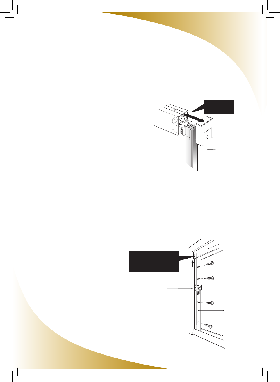
Installing the Mounting Bracket
1. Remove the backing of the adhesive strip on the back of the
Mounting Bracket.
2. Insert the bottom of the Mounting Bracket into the track of the Bottom
Rail on the hinge side of the door.
3. Push the Mounting Bracket upwards, ensuring that the top of the Corner
Cover is tight against the upper portion of the door frame.
4. Using a level, ensure that the Mounting Bracket is positioned plumb.
Then press the Mounting Bracket rmly against the door frame, allowing
the adhesive tape to temporarily hold it in place.
5. Move the Sliding Bar and Mesh off to the side as indicated in
the illustration.
6. Using the provided screws, secure the Mounting Bracket to the
door frame.
7. Return the Sliding Bar and Mesh back to its original position, in front of
the Mounting Bracket.
9
Door Frame
(Top)
Sliding Bar
Mounting Bracket
Door Frame
Installing the Top Rail and Catch Frame
Installing the Top Rail
1. Remove the backing of the adhesive tape on the
top of the Top Rail.
2. Insert the Rollers at the top of the Sliding Bar
into the Top Rail, then push the Top Rail into the
Corner Cover on the top of the
Mounting Bracket.
3. Position the Top Rail along the top of the door
frame at a 90º angle to the side
mounting surfaces.
4. Making sure that the Top Rail is tight against the
side of the door frame opposite the
Mounting Bracket, press rmly in place,
allowing the adhesive tape to temporarily hold
it in place.
5. Using the 5/8” (16mm) screws provided, secure
the Top Rail to the door frame.
Installing the Catch Frame
1. Insert the bottom of the Catch Frame inside the
Bottom Rail and the top of the Catch frame into the
Top Rail. Position it against the door frame on
the opposite side of the Screen Housing Assembly.
2. Lift the Catch Frame upward into the Top Rail
as far as it will go, and secure to the door frame
using the provided wood screws.
Top Rail
Catch Frame
Latch
Door Frame
Push up the top of the
Catch Frame all the way
into the Top Rail
10
Push into the
Corner Cover
Corner Cover
Mounting Bracket
Insert Rollers
as shown
Indice
Altri manuali Phantom Porta


