Philips EasyKey 1000 Series Manuale utente

EasyKey
1000 series
DDL101-3HBS
Indoor lock
User manual
www.philips.com/support
Sign your product up and get support at www.philips.com/support


1
Contents
1. Important Information 02
Safety
Caution
Disposal of used products and
batteries
2. Assembly 03
Packing list
Exploded views
Notice before assembling
Assembly procedures
3. Get to know your lock 08
Exterior unit
Interior unit
4. Settings 09
Initialization
Fingerprint
Lock mode
Mute mode
Default settings
Application binding
5. Get to use your lock 15
Outdoor/ indoor unlock
Outdoor/ indoor locking
6. Indicators 16
Low battery alert
Lock-out alert
Battery replacement
How to apply external power supply
7. Troubleshooting 16

2
1. Important information
Safety
◆Before using this product, please read and
understand all instructions. Damage caused by
failure to follow the instructions is not covered
by the warranty.
◆Use only the accessories/components specied
by the manufacturer.
◆Please use alkaline batteries or lithium polymer
batteries that are specically recommended
for this product, or use batteries of the same
specications and type.
◆Do not forcibly disassemble the product to
trigger an alarm or damage the product.
◆Do not scrape the ngerprint sensor with
sharp objects, as this may cause permanent
damage.
◆Do not expose products to places that have
water leakage or splashing.
◆Do not expose the product to corrosive
substances to prevent damaging the protective
cover.
◆Do not hang objects on the handle in case it
might aect the use of the lock.
◆Please use a soft cloth soaked in water to
remove ngerprints/dirt left on the surface of
the assembly.
◆Do not remove the batteries during setting up
and operating.
◆Please follow the assembly instructions to
install the product and keep the relevant sealed
stickers properly.
◆Please change the default master PIN code
immediately after completing the installation and
troubleshooting, properly store the mechanical
keys, and do not disclose the PIN codes to others.
◆Please replace all batteries immediately when
a low battery alarm appears.
Caution
◆ Do not place the batteries near ignition
source to avoid explosion.
◆ Do not use any power supply that does
not meet the safety requirements to power
up the product.
◆Do not connect the 2 poles of the batteries
to metals to avoid a short circuit that may
cause an explosion.
◆ Please make sure installation or any
component replacement is performed by
Philips, a Philips authorized service center
or professional technicians.
◆ Do not use accessories or parts
manufactured by others or not expressly
recommended by Philips. The use of
such accessories and parts may void the
warranty.
Disposal of used
products and batteries
◆ You can have your locks taken back at
authorized Philips service centers. You will
receive appropriate compensation if your
products meet our conditions.
◆ Please familiarize yourself with the local
collection system for electronic products.
◆ Please follow local regulations and do not
discard used products and batteries into
ordinary household waste.
◆ Please familiarize yourself with the local
regulations for recycling batteries. Proper
disposal of batteries can help prevent
negative effects on the environment and
human health.

3
Exterior unit Interior unit Drilling template Mortise
Lock cylinder
cover
User manual Warranty card Quality certicate
AAA batteries Strike plate Strike box Installation kit
Interior lock
cylinder cover base
Interior unit base
Warranty
Card
Easy
Key
Packing list
This packing list is for reference only. Please refer to the actual packing items.
2 Assembly
EasyKey
1000s eries
DDL101-3HBS
Indoor lock
User manual
www.philips.com/ support
Signyo urprodu ct up and get suppo rt at ww w.philips. com/support
1
5
9
13
2
6
10
14
3
7
11
4
8
12

4
1.Interior unit x1
2.Lateral screw x4
3.Interior unit base x1
4.Mortise x1
5.Hollow square shaft x1
6.M5 screw tube x4
7.Exterior unit x1
8.Interior lock cylinder
cover x1
9.Anchor screw x4
10.Interior lock cylinder
cover base x1
11.Anchor screw for lock
cylinder x1
12.Exterior lock cylinder
cover x1
13.Lock cylinder x1
1
2 3
4 5
6
7
911 12
8
13
10
Exploded views

5
This product applies to doors with swing directions as follows: left-hand inswing,
left-hand outswing, right-hand inswing, and right-hand outswing.
Adjust the latch bolt direction based on the needs of inswing and outswing doors.
The installation kit provided is applicable for doors with a thickness of 35-60mm. If your
door thickness falls outside this range, please consult our local dealer for further assistance.
Left-hand inswing Right-hand inswing
Left-hand outswing Right-hand outswing
Push upward
Push the latch
bolt down, rotate
it in the opposite
direction, and allow
it to rebound to its
original position.
Notice before assembling
Adjustable latch instructions
Left-hand swing Right-hand swing
Attention

6
1 2
3
During installation, the deadbolt should not
be protruding or extending out.
4
The following assembly instructions are for right-hand swing doors. For left-hand
swing doors, please read and understand the 'Notice before assembling' section,
and follow the 'Adjustable latch instructions' to adjust the latch bolt direction
accordingly.
Drill holes according to the drilling
template, then place the mortise
inside the frame and use the two
anchor screws to secure the mortise.
Place the interior unit base rmly
against the inside of the door and
secure it with two screws. Similarly,
align the base of the interior lock
cylinder cover base against the inside
of the door and secure it with two
screws.
Align the hollow square shaft on the
exterior unit with the rotating opening
on the mortise. Align the exterior lock
cylinder cover with the lock cylinder,
ensuring that the exterior unit and the
exterior lock cylinder cover are tightly
attached to the outside of the door.
Refer to the diagram for instructions
on opening the battery cover.
Assembly procedures
Push the cover as
indicated by arrow
Attention

7
5 6
7 8
Connect the cable to the interior
unit. Then assemble the interior unit
and the interior lock cylinder cover.
Use the provided screws to secure
the interior unit and the interior
decorative ring on both sides.
Install the battery, close the battery
cover, and attach the strike plate to
complete the assembly process.
Verify that the lock cylinder, thumb
turn and mechanical key are
functioning properly and ensure
that all components are securely
connected.
Insert the lock cylinder and secure
it with the screw as shown in the
diagram.
Insert the cable as
shown in diagram
After installing the strike plate, please
ensure the door opens and closes smoothly.
Attention
AAA
AAA
AAA
AAA

8
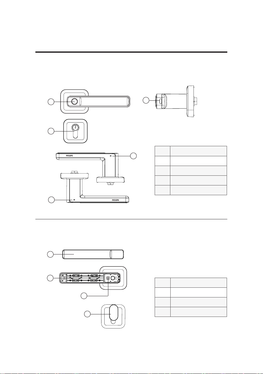
Exterior unit
Interior unit
①Fingerprint sensor
②Type-C port
③Mechanical keyhole
④Indicator 1
⑤Indicator 2
①Battery cover
②Battery compartment
③Setup button
④Thumb turn
This packing list is for reference only. Please refer to the actual packing items.
3 Get to know your lock
12
5
4
3
2
3
1
4
Questo manuale è adatto per i seguenti modelli
1
Indice
Altri manuali Philips Serratura