PIPE LIGHTING PIPE 2 Istruzioni per il montaggio

USER’S
MANUAL
GUIDE
pipe 2
pipe 4
pipe 8

Product package..........................................................................................................................................................................................................
Technical specifications.............................................................................................................................................................................................
Usage precautions.......................................................................................................................................................................................................
Getting ready for operation......................................................................................................................................................................................
Connecting the controller..........................................................................................................................................................................................
Controller protective cover ......................................................................................................................................................................................
Underwater usage.......................................................................................................................................................................................................
Controller settings......................................................................................................................................................................................................
DMX Menu......................................................................................................................................................................................................
User Menu.....................................................................................................................................................................................................
User Menu: Separate Mode.....................................................................................................................................................................
User Menu: DMX_seq................................................................................................................................................................................
User Menu: Overdrive mode...................................................................................................................................................................
User Menu: Max. Power............................................................................................................................................................................
User Menu: Step Change Ratio..............................................................................................................................................................
User Menu: Smooth Transition..............................................................................................................................................................
User Menu: Reset.......................................................................................................................................................................................
Resetting CRMX network adapter........................................................................................................................................................
Finishing work and order of stacking the equipment in the bag...............................................................................................................
Warranty........................................................................................................................................................................................................................
CONTENTS
2
3
4
5
7
8
9
10
11
12
13
15
16
18
19
20
21
22
23
24
User's Manual
2
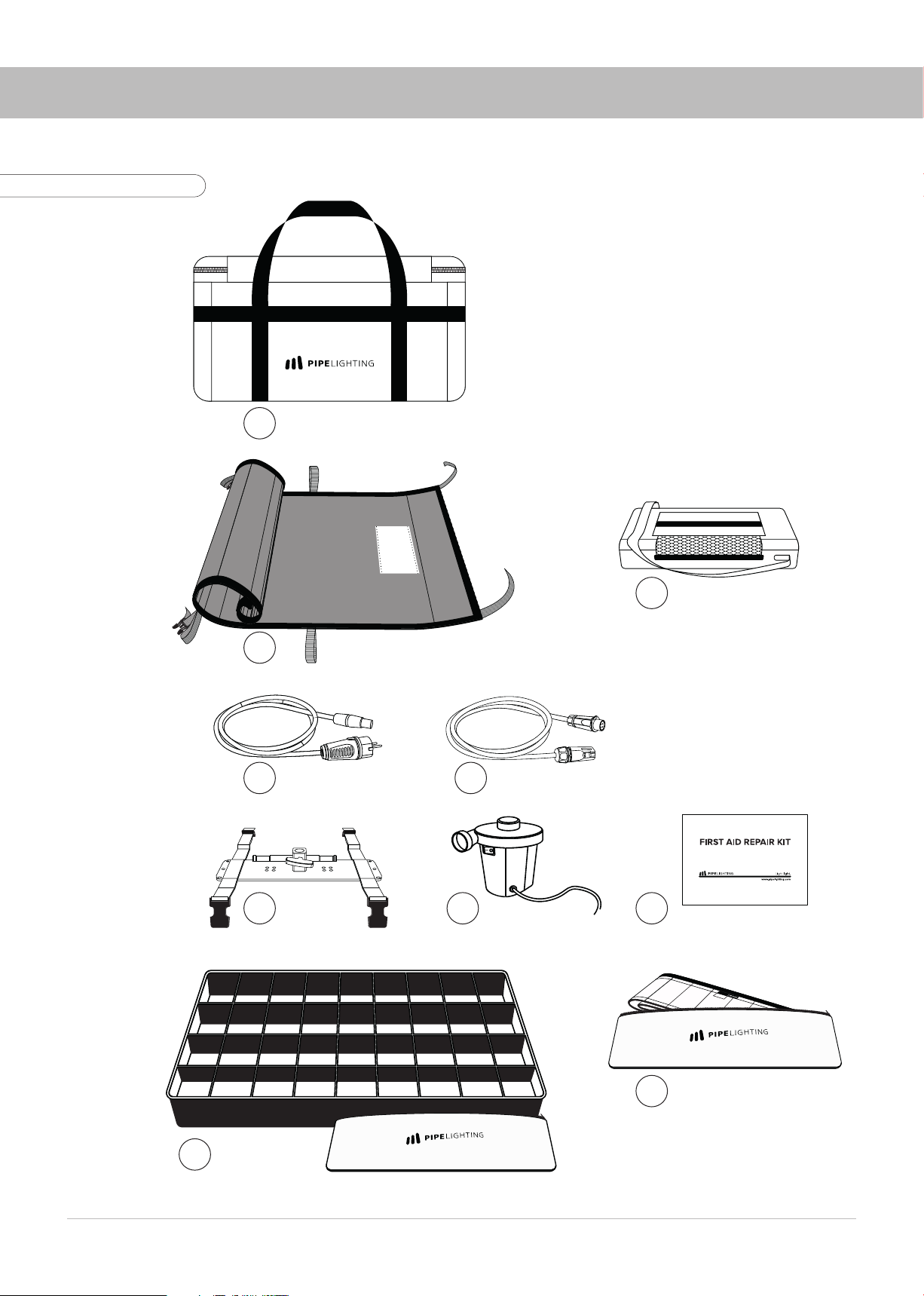
PRODUCT PACKAGE
1
2
3
4 5
6 7 8
10
9
1. Transportation bag
2. Lamp Head – “Pipe”
3. Controller in bag
4. AC-Cable
5. Extension cable (5m)
6. Mounting frame with straps
7. Air pump
8. Repair Kit
9. Eggcrate (Soft grid) in bag
10. Skirt in bag
Fig. 1. Product package

3
TECHNICAL SPECIFICATIONS
Model PIPE 2 PIPE 4 PIPE 8
Lamp head size
(L × W × H), cm 65×35×20 135×35×20 260×30×30
Lamp head weight,
kg 0,7 11,7
Voltage, V 24 24 24
Current per color, A 4 8 16
Total power rating, W 160 320 650
CRI 95+
CCT 2600 K – 5700 K
Lumens 5490 10980 21960
Operation Conditions
Controller
Operating T, 0C Min: -15C / Max: +40C
Storage T, 0C 15-20C
IP Rating IP20
Lamp Head
Operating T, 0C Min: -15C / Max: +40C
Storage T, 0C 15-20C
IP Rating IP67

User's Manual
4
USAGE PRECAUTIONS
DO NOT SMOKE
DURING OPERATION!
AVOID SHARP OBJECTS!
DO NOT FOLD OR
STORE WET EQUIPMENT
AVOID OVERINFLATING!
LAMP HEAD GETS HOT!
DO NOT USE THE FIXTURES
NEAR HOT SURFACES OR OBJECTS
USING THE FIXTURE UNDER DIRECT SUNLIGHT
OR HIGH TEMPERATURES MORE THAN 30
CHECK THE PRESSURE!
DO NOT TOUCH THE LAMP HEAD
WITH DIRTY HANDS!
DO NOT WEAR GLOVES!
ROLLING THE LAMP HEAD THE INNER
DIAMETER SHOULD BE 5CM MAX.!
DO NOT FOLD THE LAMP HEAD!
AVOID TENSION
ON POWER AND CONTROL CABLES!
ROLL WITH
THE LEDS INWARDS ONL
Y!
Fig. 2. Usage precautions

5
1. Open the case, take the lamp head with clean hands. Unroll the lamp head on a flat clean surface
without any sharp or hot objects (Fig. 3).
2. The device can be used both inflated and deflated (Fig. 4).
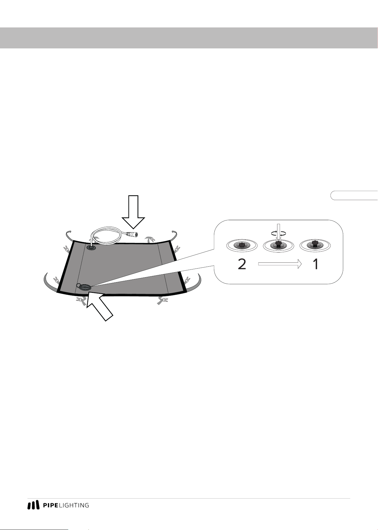
3. Open the air valve cover and make sure that the air valve button is in position 2. The positions of
the air valve button 1 and 2are shown in Fig. 5.
4. Inflate the lamp head with the air pump provided by bringing the pump to the valve. Make sure the
lamp head had reached its shape. Do not overinflate! Move the pump away from the valve and quickly
move the valve button to position 1. If necessary, inflate the lamp head slightly through the closed valve
by pushing the pump on the valve button. To release pressure push the valve.
GETTING READY FOR OPERATION
Fig. 3
Fig. 4
Fig. 5

User's Manual
6
mounting on tripod
5. Fold the corners of the lamp head with Velcro to the end face, fasten with Velcro as shown in Fig.6.
6. Attach the mounting pad to the lamp head (Fig.6). Adjust the fastening straps on the rear side of
the device.
7. Fix the instrument in operating position on the tripod.
8. Remove the protective cover from the lamp head head. Carefully fold the protective cover with
the clean side inwards and put it into the bag (Fig.7).
9. If necessary, attach a soft grid/eggcrate and/or skirt (included) to the instrument head.
GETTING READY FOR OPERATION
clean side
Fig. 6
Fig. 7
Fig. 8

7
CONNECTING THE CONTROLLER
1. Align the connectors of the signal cable and the controller as shown in Fig.9.
2. Connect the power AC-cable to the connector on the body and the 220V socket.
3. Switch on the controller (Fig.10).
AC-Cable Extension cable
ON toggle switch
Fig. 9
Fig. 10

User's Manual
8
CONTROLLER PROTECTIVE COVER
The controller protective cover has two operating positions. Position 1(Fig. 11) with air vent open
is the main operating position. When used outdoors during rainfall, the flaps of the cover should be
folded to position 2 (Fig. 11).
Fig. 11
Fig. 12
It is also possible to use the flaps of the flap to form a mounting bracket with which the controller
can be mounted on a tripod (Fig. 12).
9
UNDERWATER USAGE
You can use Pipe Lighting products under water. To do so please take all the air out of the fixture
with the back side of the air pump. Make sure to fix the lamp head properly under water using weights
and/or frame.
Maximum guaranteed water depth: 2m.
ATTENTION: Make sure to close the air valve (put it in 1position) and the cap of the valve on the
lamp head! Danger of moisture entering the lamp head! The cable connector must stay above the
water surface! (Fig.13)
The valve is not airtight, it reduces, but does not eliminate the possibility of moisture entering
the device!
Fig. 13.
KEEP IT DRY!
PUT THE AIR VALVE IN 1POSITION AND CLOSE THE CAP!
Questo manuale è adatto per i seguenti modelli
2
Indice
Altri manuali PIPE LIGHTING Attrezzatura di illuminazione


