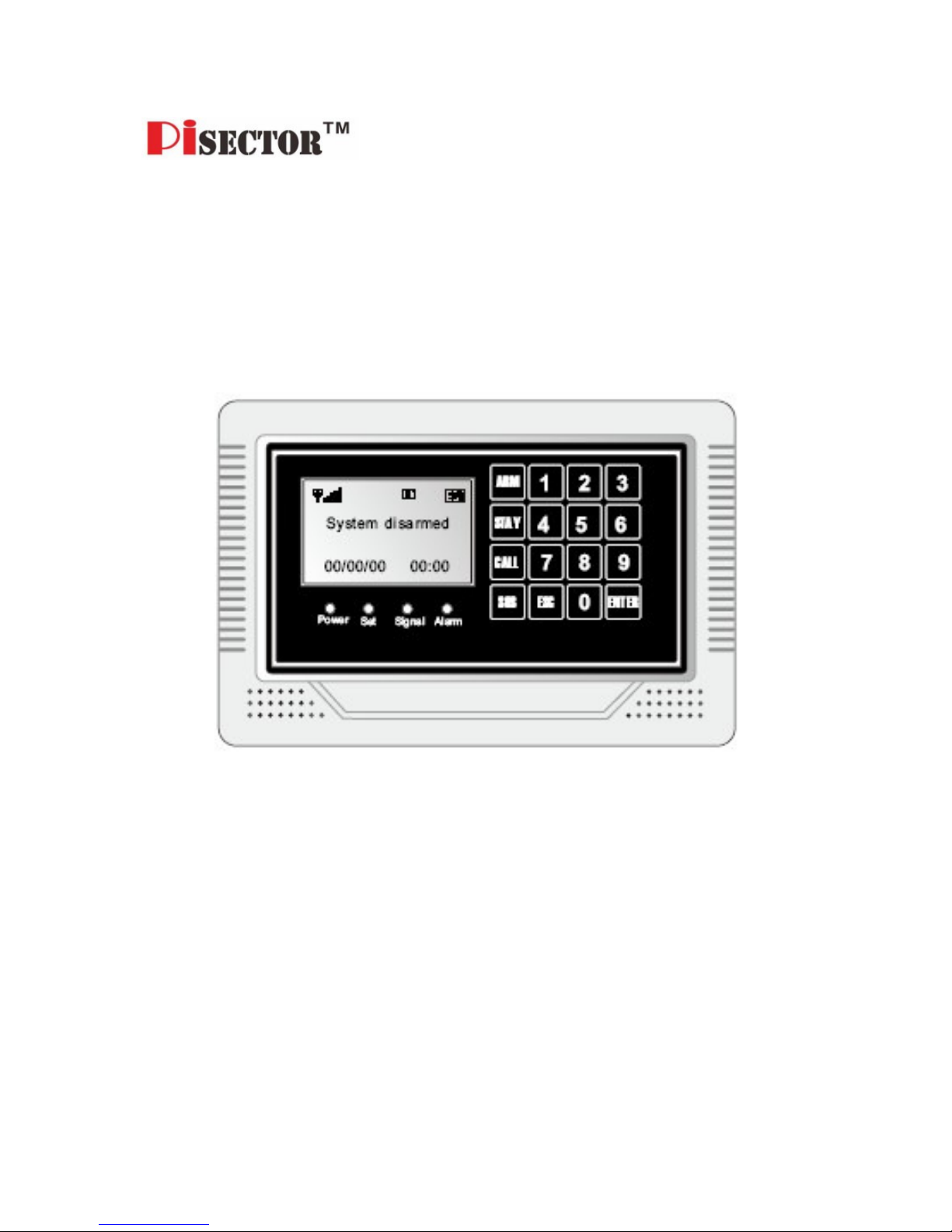
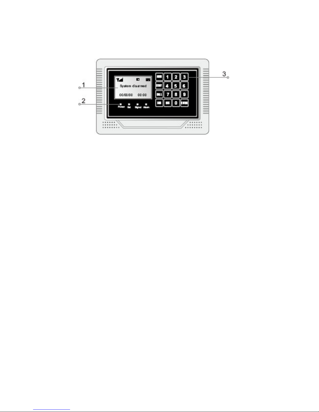
Pisector GSM-03 Manuale utente

PiSector Professional
Wireless GSM Alarm System
User Manual (GSM-03)
Read manual fully before use.
PiSector nc., USA, www.pisector.com

1.
WHAT'S N THE BOX .................................................................. 4
2.
MA N FEATURES ........................................................................ 5
3.
KNOW YOUR SYSTEM ............................................................... 6
4.
SYSTEM N T AL ZAT ON ........................................................... 9
5.
SYSTEM SETT NG NSTRUCT ONS ........................................ 10
5.1.
E
NTERING
S
ETTING
M
ODE
..................................................... 10
5.2.
A
DDING
R
EMOTE
C
ONTROLLER
.............................................. 11
5.3.
D
ELETING
R
EMOTE
C
ONTROLLER
........................................... 13
5.4.
C
ODING
D
EFENSE
Z
ONE
........................................................ 14
5.5.
D
ELETING
D
EFENSE
Z
ONE
..................................................... 16
5.6.
S
ETTING
D
EFENSE
Z
ONE
P
LACES
........................................... 17
5.7.
S
ETTING
D
EFENSE
Z
ONE
M
ODES
........................................... 19
5.8.
S
ETTING
D
EFENSE
Z
ONE
S
IREN
............................................. 20
5.9.
A
LARM
D
ELAY
S
ETTING
......................................................... 21
5.10.
A
DDING
P
HONE
N
UM ER
....................................................... 22
5.11.
D
ELETING
P
HONE
N
UM ER
.................................................... 23
5.12.
A
DDING
SMS
C
ELL
P
HONE
N
UM ER
...................................... 24
5.13.
D
ELETING
SMS
C
ELL
P
HONE
N
UM ER
................................... 25
5.14.
V
OICE
R
ECORDING
............................................................... 26
5.15.
V
OICE
R
ECORDING
R
EPLAY
................................................... 27
5.16.
S
ETTING
S
YSTEM
D
ATE
......................................................... 28
5.17.
S
ETTING
S
YSTEM
T
IME
.......................................................... 29
5.18.
S
CHEDULING
T
IMELY
A
RM
...................................................... 30
5.19.
S
CHEDULING
T
IMELY
D
ISARM
................................................. 31
5.20.
W
IRELESS
S
IREN
C
ODING
...................................................... 32
5.21.
W
IRELESS
S
IREN
C
ODE
E
NCRYPTION
..................................... 33

3
5.22.
C
HANGE
O
PERATION
P
ASSWORD
............................................ 34
5.23.
C
HANGE
P
ROGRAM
P
ASSWORD
.............................................. 35
5.24.
S
ETTING
A
RM
D
ELAY
T
IME
..................................................... 36
5.25.
S
ETTING
A
LARM
(C
ALL
O
UT
)
D
ELAY
T
IME
................................ 37
5.26.
V
OICE
P
ROMPT
S
ETTING
....................................................... 38
5.27.
S
IREN
P
ROMPT
S
ETTING FOR
R
EMOTE
C
ONTROLLER
............... 39
5.28.
ACKLIGHT
S
ETTING
............................................................. 40
5.29.
S
IREN
S
ETTING IN
“E
MERGENCY
”
M
ODE
.................................. 41
5.30.
A
RM
/
D
ISARM
SMS
N
OTIFICATION
......................................... 42
5.31.
L
ANGUAGE
S
ETTING
.............................................................. 43
5.32.
F
ACTORY
R
ESET
................................................................... 44
5.33.
P
ASSWORD
R
ESET
................................................................ 45
6.
SYSTEM USAGE NSTRUCT ONS ........................................... 46
6.1.
O
UT
A
RM
............................................................................. 46
6.2.
H
OME
A
RM
........................................................................... 47
6.3.
D
ISARM
................................................................................ 48
6.4.
A
NSWER
A
LARM
C
ALL
........................................................... 49
6.5.
R
EMOTE
C
ONTROL
................................................................ 50
6.6.
E
MERGENCY
A
LARM
C
ALL
...................................................... 51
6.7.
U
SE AS
T
ELEPHONE
.............................................................. 52
6.8.
A
LARM
H
ISTORY
R
EVIEW
....................................................... 53
7.
TECHN CAL SPEC F CAT ONS ................................................ 54
8.
CARE AND MA NTENANCE ..................................................... 55

4
1. What's n The Box
1 x Main Unit Panel
2 x Remote Controller
1 x Indoor Siren
1 x Passive IR Sensor
1 x Door Gap Sensor
1 x Power Adapter
1 x User Manual

5
2. Main Features
Quad-band worldwide cellular phone (900/1800/850/1900 MHz).
Elegant touch keypad with easy to use detailed menu system.
128×64 lattice LCD screen with clock display (English/Chinese)
4 wired and 10 wireless (433MHz) defense zones; each wireless
zone supports up to 10 sensors.
Support for up to 8 remote controllers.
uilt-in loud speaker and intelligent voice announcer.
Auto-play 10-second pre-recorded voice message on alarm
(useful for giving address/GPS position to emergency services).
Up to 6 phone numbers to dial out on alarm.
Up to 3 SMS numbers: to send SMS to when alarm.
Remote control by phone to arm, disarm, or intercom (listen-in).
One-touch control: ARM (out arm), STAY (home arm) via touch
keypad or arm and disarm via remote controller or telephone.
4 Arm Modes: out arm, home arm, delay arm and timely arm for
scheduling arm / disarm times).
8 Defense Zone Places: SOS, fire, gas, door, hall, window,
balcony, and boundary.
4 Arm Delay Modes: Real-time (immediate), 01-99 second delay,
24 hours (always-armed even if system disarmed), Disable
Alarm calls have priority over all other calls if the device is busy.
Direct wireless coding of any additional wireless accessories.
Alarm History to store the last 30 alarm records.
Arm via the main unit panel, remote controller, or remote call by
phone.
SMS alert of power failure and recovery.
uilt-in Lithium-Ion battery with automatic recharge.

6
3. Know Your System
1. LCD Screen: Resolution: 128×64; English and Chinese display.
2. LED Status ndicators
POWER: power and system activity indicator:
- fast flashing once per second: system is searching for GSM signal.
- slow flashing once per 3 seconds: system is in ready mode.
SET: is ON when the system enters setting mode.
S GNAL: wireless signal indicator (used by wireless sensors).
ALARM: is ON if any sensor triggers or sets off an alarm.
3. Touch Keypad: Resistive Touch Panel requires gentle key pressing.
Do not press the keypad heavily as this may reduce its sensitivity.
ARM: press to enter OUT ARM status (gives you 40 seconds to
leave home before system is armed).
STAY: press to enter HOME ARM status (deactivates all sensors
with Home defense zone mode and activates all other sensors).
CALL: For making phone calls. Enter the number you want to call,
and then press this CALL button. Press again to end call (hang up).
SOS: press to raise an emergency alarm.

7
ESC: clears the input content or back to last operation.
ENTER: confirms current command or operation.
4. Wired Ports
1
SIREN+
Positive of siren (red cable)
2 SIREN- Negative of siren (black cable)
3
T_VCC
Reserved
port
4
CLK
Reserved
port
5 DATA Reserved port
6 T_GND Reserved port
7
GND
GND
8 Zone 1 Wired sensor 1: support both NO and NC
9
GND
GND
10 Zone 2 Wired sensor 2: support both NO and NC
11
GND
GND
12 Zone 3 Wired sensor 3: support both NO and NC
13
GND
GND
14 Zone 4 Wired sensor 4: support both NO and NC
15 GND GND

8
5. nternal Backup Battery Switch.
6. S M Card Slot: Please pay attention to the direction arrow marked
on the slot: “LOCK” / “OPEN”. Do not insert or take out the SIM card
when the main unit panel is powered on.

9
4. System nitialization
Correct initialization of the main unit panel is important to its normal
working and lifespan.
1. Connect the wired accessories that you need.
2. Insert the SIM card.
3. Connect the power adapter. The main unit panel will start
self-inspection and the POWER indicator LED will flash once per
second. If this LED does not light on, you need to restart the main
unit panel. Please do it at least 10 seconds later as repeated power
on and off in short times will shorten the service life of the system.
4. The POWER indicator will flash once every 3 seconds after finding
GSM network successfully. This is the normal system state.
5. Turn on the internal backup battery switch on the back of the main
unit panel.
6. Check the GSM signal icon on the LCD screen. Signal less than 3
bars will affect normal performance. Please place the main unit
panel at a place with good GSM signal reception.

10
5. System Setting nstructions
5.1. Entering Setting Mode
All settings have to be done in the setting mode.
Use keys 2 / 8 / 4 / 6 as direction keys (up / down / left / right).
At the disarm state, input your 6-digit password (default: 888888), then
press ENTER. The main unit panel will sound a beep and the SET
indicator lights on. The screen will display Remote Control menu.
Fig 1: disarm status
Fig 2: please enter password
Fig 3: press ENTE to set
Indice
Altri manuali Pisector Sistema di sicurezza

Pisector
Pisector GSM-01 Manuale utente

Pisector
Pisector PS03 Manuale utente

Pisector
Pisector GS08 Manuale utente

Pisector
Pisector GSM-01 Manuale utente

Pisector
Pisector Motion sensor Manuale utente

Pisector
Pisector PS03 Manuale utente

Pisector
Pisector P09 series Manuale utente

Pisector
Pisector GSM-06 Manuale utente

Pisector
Pisector GS08 Manuale utente

Pisector
Pisector GS08 Manuale utente
Manuali Sistema di sicurezza popolari di altre marche

EDM
EDM Solution 6+6 Wireless-AE Manuale utente

Highway Safety Group
Highway Safety Group EA401 Manuale utente

Siren
Siren LED GSM Manuale utente

Detection Systems
Detection Systems 7090i Istruzioni per il montaggio

Se-Kure Controls
Se-Kure Controls MicroMini SK-4841 Manuale utente

Siemens
Siemens FDM273 Manuale utente


