Plura RUBIDIUM Series Manuale utente


Page 4 Option “I” IRIG-B Reader
A1 Revision History
No.
Date
Subject
0.n
Preliminary documents, changes without notice.
1.0
August 19, 2016
First released document.
1.1
May 10, 2019
Added date formats and TC_Link.
1.2
September 30, 2019
Changed address of Plura Europe GmbH.
1.3
December 2, 2020
Re-formatted in new design.
A2 Copyright
Copyright © Plura Europe GmbH 2016-2019. All rights reserved. No part of this publication
may be reproduced, translated into another language, stored in a retrieval system, or
transmitted, in any form or by any means, electronic, mechanical, photocopying, recording, or
otherwise without the prior written consent of Plura Europe GmbH.
Printed in Germany.
Technical changes are reserved.
All brand and product names mentioned herein are used for identification purposes only and
are trademarks or registered trademarks of their respective holders.
Information in this publication replaces all previously published information. Plura Europe
GmbH assumes no responsibility for errors or omissions. Neither is any liability assumed for
damages resulting from the use of the information contained herein.
For further information please contact your local dealer or:
Plura Europe GmbH
Binger Weg 12
D- 55437 Ockenheim
Phone: +49 6725 918 006-70
Fax: +49 6725 918 006-77
E-Mail: info@plurainc.com
Internet: http://www.plurainc.com
A3 General Remarks
This manual is a supplement to the “Functional Description & Specifications” of the XV
appropriate module.
It describes those additional features which are made available assembling an additional
board and flashing a special firmware with OPT75.

Option “I” IRIG-B Reader Page 5
1 Hardware
1.1 Additional Board
Option “I“ requires assembling an additional board.
The rear plate of the module receives a RJ45 jack additionally.
This board can be assembled for RUB1 as well as for RUB3 versions of XV.
LOOPOUT
VIDEOIN
VIDEOOUT
Alpermann+Velte
IRIG
IN
8.....1

Page 6 Option “I” IRIG-B Reader
1.2 Connections
Pin assignments
IRIG IN
RJ45 jack
1: GPI_1
2: GPI_2
3: IRIG_IN_A
6: IRIG_IN_B
4: GND
5: do not connect
7: GPI_3
8: GPI_4
Signal descriptions
GND
Signal ground.
IRIG_IN_A
IRIG_IN_B
IRIG-B (Time Code) input.
Balanced IRIG-B
Cinch/RCA/BNC
Unbalanced IRIG-B
Pin 3: REF_IN_A
Pin 6: REF_IN_B
Pin 4: GND Signal -
GND
Signal +
GPI_1 ... GPI_4
General Purpose In/Out: inputs or outputs for digital signals
according to application.
Programmable functions.

Option “I” IRIG-B Reader Page 7
1.3 Specifications
IRIG-B Input
Supported Formats
IRIG-B: Amplitude modulated 1 kHz carrier signal, balanced.
IRIG-B 123 or IRIG-B 127 according to IRIG STANDARD 200-04;
AFNOR time code according to AFNOR NF S 87-500.
Connector
RJ45: Signals IRIG_IN_A/IRIG_IN_B
Input
Balanced or unbalanced signals
Impedance: 680 Ω
Mark Amplitude: 1 Vpp to 5 Vpp
Space Amplitude: 0.5 Vpp to 2.5 Vpp
Mark-to-Space Ratio: 2/1 to 6/1
GPI
GPI_1 ... GPI_4:
Input specification
Input “Low“: -2.0 to +1.0 V
Input “High“: +3.0 to +24.0 V
Impedance: ≈ 4.7 kΩ
Frequency: 0 - 1 MHz
GPI_1 ... GPI_4:
Output specification
Open Collector output of an NPN transistor at 4k7 pull-up
resistor (5 VDC). Max. power dissipation: 200 mW.
“High“ state: 4.3 V (no load).
“Low“ state: output switched to GND.
Max. collector current: 100 mA DC, fused by a 100 mA auto-
recovery fuse.
Collector-emitter saturation voltage: @100 mA: typ. 200 mV
(600 mV), @10mA: typ. 90 mV (250 mV).
Frequency: 0 - 150 kHz.

Page 8 Option “I” IRIG-B Reader
2 Functions
2.1 IRIG-B Reader
Option “I“ adds IRIG-B reader functionality to the module:
•Read IRIG-B and visibly insert time and user data.
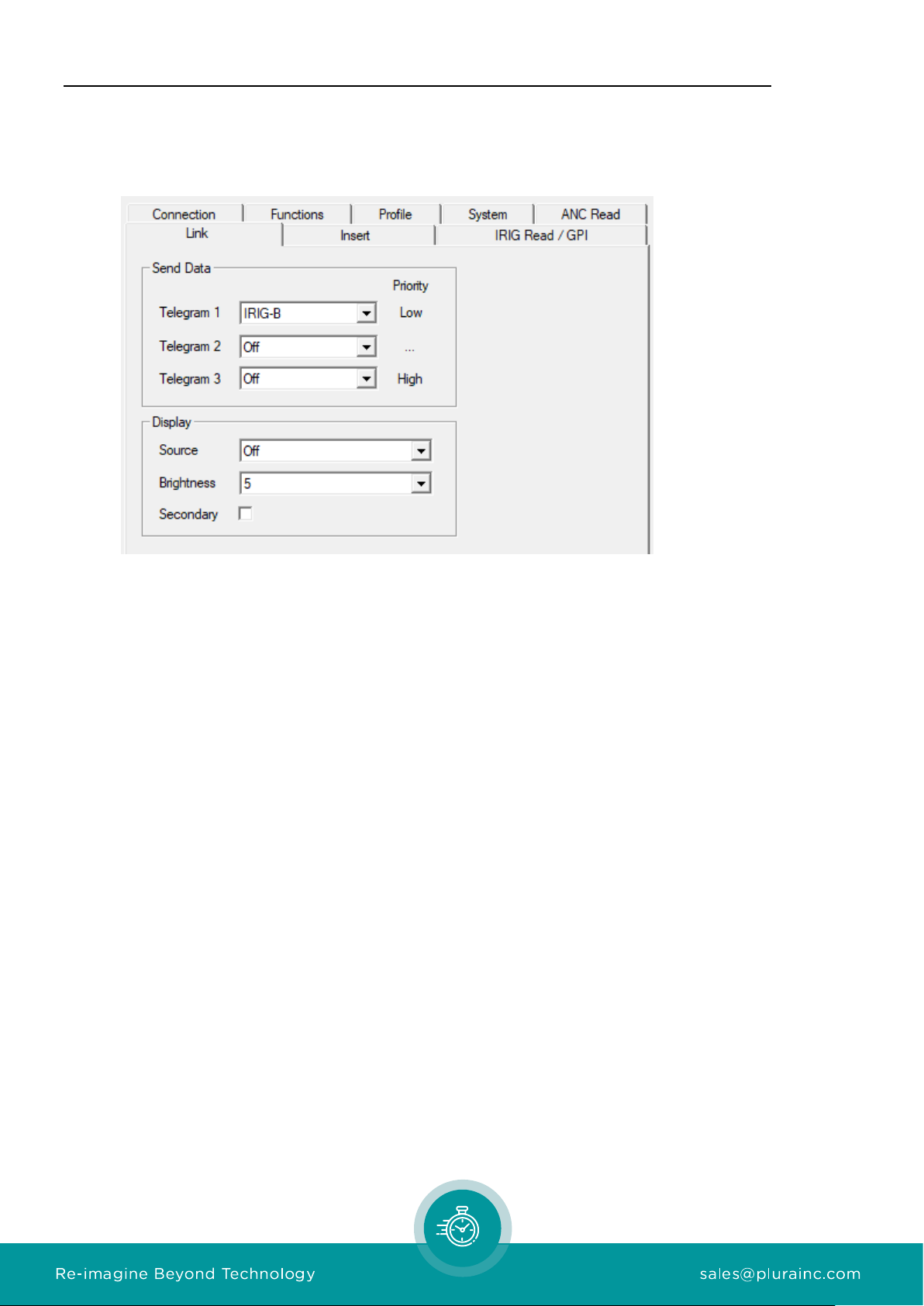
At the IRIG Read / GPI page of the configuration tool, three formats can be selected. Please
select according to the format of the input signal.
Decoding a date makes the difference:
IRIG-B 123: This format according to IRIG STANDARD 200-04 does not include information
about the current year. So, the year will be read out of the battery buffered real time clock of
the module after power has turned on. It is possible to set the year manually utilizing the
configuration tool. Turn of the year will be proceeded automatically. This format conveys “day
of year”. If the year is known, day and month can be calculated.
IRIG-B 127: This format according to IRIG STANDARD 200-04 includes year information (two
digits 00 –99, meaning 2000 –2099). Together with the “day of year” information the date
can be calculated.
AFNOR NF S 87-500: The format according to NF S 87-500 includes day, month, and year
information. So, the date can be completely decoded.

Option “I” IRIG-B Reader Page 9
2.2 IRIG-B Inserter
Option “I” enables to insert values from the IRIG-B reader visible to video. The module has to
receive the following set-up at the Insert page:
“Source = IRIG-B“
“Format = IRIG-B“
Data will be displayed in the following format:
208 : 10 : 59 : 28 : 96
Day of
Year HH:MM:SS:1/100
It’s also possible to use the “Date”formats like “Date, DD MM YYYY”to insert local date if
provided by IRIG source.
Page 10 Option “I” IRIG-B Reader
2.3 TC_Link
IRIG-B data can be distributed to other video inserters over TC_Link. This allows to insert the
same IRIG-B code to different video streams.
If another video module like XV receives IRIG-B data over TC_Link it will use it as its IRIG-B
data source for the IRIG-B inserter.
Altri manuali per RUBIDIUM Series
7
Questo manuale è adatto per i seguenti modelli
1
Indice
Altri manuali Plura Hardware per computer

Manuali Hardware per computer popolari di altre marche

EMC2
EMC2 VNX Series Manuale del proprietario

Panasonic
Panasonic DV0PM20105 Manuale utente

Mitsubishi Electric
Mitsubishi Electric Q81BD-J61BT11 Manuale utente

Gigabyte
Gigabyte B660M DS3H AX DDR4 Manuale utente

Raidon
Raidon iT2300 Manuale utente

National Instruments
National Instruments PXI-8186 Manuale utente


