PMI PSSA-10K230M-50 Manuale

DOCUMENT NUMBER
MAN-70009, REV A
SERIAL NUMBER
170I001
SOLID STATE HIGH POWER WIDE BAND
AMPLIFIER
MODEL: PSSA-10K230M-50
OPERATING AND MAINTENANCE
INSTRUCTIONS
Reliant EMC LLC
3311 Lewis Ave
Signal Hill, CA 90755
Tel.: (408) 916 - 5750
E-Mail: [email protected]
Web: www.reliantemc.com
Distributed by

MAN-70009, REV A Page 2of 35
TABLE OF CONTENTS
SECTION DESCRIPTION PAGE
1.0 INTRODUCTION............ ................................................................................................................... 3
2.0 GENERAL DESCRIPTION ................................................................................................................ 5
3.0 Controller Operation ………….......................................................................................................... 6
4.0 GENERAL INFORMATION
4.1 Scope of This Manual .......................................................................................................... 13
4.2 Operation Overview............................................................................................................. 13
4.3 N/A
4.4 General Specifications ......................................................................................................... 15
4.5 Protection Circuits ............................................................................................................... 16
4.6 Status Indicators, Controls and Connectors ......................................................................... 16
4.7 Front Panel Status Indicators ............................................................................................... 18
5.0 PRINCIPALS OF OPERATION
5.1 Proper Usage and Warnings................................................................................................. 20
6.0 Remote INTERFACE
6.1 Introduction........ ................................................................................................................. 21
6.2 RS-232 ................................................................................................................. 21
6.3 ETHERNET ................................................................................................................. 22
6.4 Remote Command Format................................................................................................... 24
7.0 MAINTENANCE AND SERVICING
7.1 Periodic Maintenance........................................................................................................... 30
7.2 Servicing the Amplifier........................................................................................................ 30
7.3 Equipment Return Procedure............................................................................................... 31
8.0 WARRANTY INFORMATION........................................................................................................ 32
LIST OF FIGURES
FIGURE DESCRIPTION PAGE
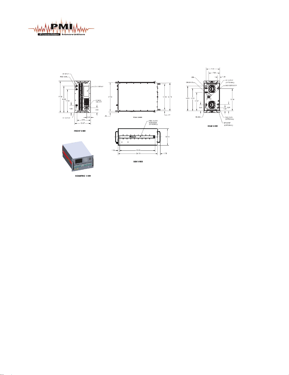
1.0 OUTLINE DRAWING ................................................................................................................... 4
10.0 SYSTEM BLOCK DIAGRAM ......................................................................................................... 14
11.0 REAR PANEL ILLUSTRATION...................................................................................................... 17
LIST OF APPENDICES
APPENDIX DESCRIPTION PAGE
A DATA SHEETS .................................................................................................... 33
B DRAWINGS.......................................................................................................... 34

MAN-70009, REV A Page 3of 35
SECTION 1.0
INTRODUCTION
Congratulations on the purchase of your new Wide Band Amplifier from PowerMax Innovation, Inc.
Your new Wide Band Amplifier incorporates the finest advancements in the state of the art electronics
technology available in a compact, portable and versatile package. Your Wide Band Amplifier's quality,
performance and trouble free operation depends on you thoroughly reading through this manual and
familiarizing yourself with its proper operation and usage.
Your Wide Band Amplifier comes with the following accessories, be sure to check your packaging for
the items listed below before disposing of the packaging.
CONTENTS
(For a typical Wide Band Amplifier)
Quantity Description
1 SOLID STATE High Power Wide Band Amplifier, Model PSSA-10K230M-50
1 Mating Connector or Power Line cable
1 Operation and Instruction Manual
1 Data Sheets (Included in Manual)

MAN-70009, REV A Page 4of 35
FIGURE 1.0
OUTLINE DRAWING

MAN-70009, REV A Page 5of 35
SECTION 2.0
GENERAL DESCRIPTION
The PowerMax Innovation, Inc. ( PMI ) manufactured SOLID STATE Wide Band Amplifier is a
Bench Top or rack mount amplifier providing a nominal 50 Watts of RF power from 10KHz
to 230 MHz, with output power of at least 50 Watts. The minimum saturated output power
at midband of the operating frequency range is more than 50 Watts.
The Amplifier features a touch screen 7” high resolution [800x480] color TFT Display that displays
continuous forward and reflected power metering. The display also provides the operator with operating
status and self diagnostic fault indications.
The Amplifier incorporates protection circuits that monitors and controls so the amplifier cannot be
damaged by any mismatched load.
The Amplifier has an Ethernet interface which allows the amplifier to be remotely controlled through
the use of a computer.
To operate the Amplifier, connect a single phase power line cable (220 Vac line to Neutral) 3 wires to
the Power Entry connector on the rear panel.

MAN-70009, REV A Page 6of 35
Section 3.0
SSA Controller Operation
3.1 Hardware Initialization
The local mode of operation will allow the user to exercise control over the parameters by way of button
switches located toward the right of the screen. Pressing a button switch will toggle the switch position
and will highlight its function.
Figure 2 Hardware Initialization Screen
Once the power is turned on the controller will boot and display the boot screen as shown above. It will
only be displayed for a few seconds follows by the PMI Logo screen.

MAN-70009, REV A Page 7of 35
3.2 PMI Screen
Figure 3 PMI Logo Screen
The PowerMax Innovations logo screen it is only displayed for a few seconds and is shown in above.

MAN-70009, REV A Page 8of 35
3.3 Information Screen
Figure 4 System Information and Set Time Button Screen
The Information screen displayed is the set time, Model and version description screen, it will be
displayed for a few seconds, should the set time icon be touched the adjust time and date screen will be
shown as in Fig. 5.

MAN-70009, REV A Page 9of 35
3.4 Time & Date setup menu
Figure 5: Set Time and Date Screen
Figure 5 shows the buttons for adjusting the time and date. Touch the + or – Buttons to adjust the time
and date, then save, then exit to return to the main screen.

MAN-70009, REV A Page 10 of 35
3.5 Operate Menu, RF-OFF [STANDBY]
Figure 6: OPERATE MENU
The operating menu, will come up in RF OFF-Mode. The values for Forward Power (FWD), Reflected
Power (RFL), and metering should be zero. The Gain will be at 100% at all times unless the Attenuator
is being controlled by pressing the Gain buttons Up or Down.
Indice


