POWER2SA P2SA 8K EU Manuale utente

USER MANUAL
Power2SA Super Hybrid Inverter 8-10kW

HISTORY
VERSION ISSUED COMMENTS
1.0 21-Dec.-22 First release
1.1 16-May-23 Update Chapter 4 Electrical Connection. Change CT connection from Pin 5,6
to Pin 9,10.
1.2 8-June-23 Change the cover and switch time from 1 second to 5 seconds.
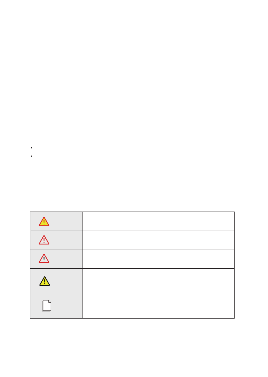
WARNING
CAUTION
DANGER
NOTICE
NOTE
Conventions
The following safety instructions and general information are used within this user manual.
Indicates an imminently hazardous situation which, if not correctly
followed, will result in serious injury or death.
Indicates a potentially hazardous situation which, if not correctly
followed, will result in serious injury or death.
Indicates a potentially hazardous situation which, if not correctly
followed, could result in moderate or minor injury.
Indicates a potentially hazardous situation which, if not correctly
followed, could result in equipment failure to run, or property
damage.
Call attention to important information, best practices and tips:
supplement additional safety instructions for your better use of the
Three phase hybrid inverter to reduce the waste of you resource.
Power2SA Inverter User Manual 3
Preface
About This Manual
This manual describes the installation, connection, APP setting, commissioning and maintenance etc.
of Power2SA inverter. Please first read the manual and related documents carefully before using the
product and store it in a place where installation, operation and maintenance personnel can reach it at
any time. The illustrations in this user manual are for reference only. This user manual is subject to
change without prior notice. (Specific please in kind prevail.)
Target Group
Power2SA inverters must be installed by professional electrical engineers who have obtained
relevant qualifications.
Scope
This manual is applicable to following inverters:
P2SA 8K EU
P2SA 10K EU

4 Power2SA Inverter User Manual
CONTENTS
Preface
1. Safety
2. Product Introduction
3. Installation
4. Electrical Connection
5. System Operation
About This Manual
Target Group
Scope
Conventions
1.1 Symbols Used
1.2 Safety Precaution
2.1 Overview
2.2 Product Appearance
3.1 Packing List
3.2 Selecting the Mounting Location
3.3 Mounting
4.1 Grounding
4.2 Meter/CT Connection
4.3 Communication Connection
5.1 Inverter Working Mode
5.2 Startup/Shutdown Procedure

6. Commissioning
7. User Interface
8. Maintenance
9. Technical Specifications
6.1 Inspection
6.2 Commissioning Procedure
7.1 LED
7.2 App Setting Guide
8.1 Routine Maintenance
8.2 Inverter Troubleshooting
Power2SA Inverter User Manual 5
Safety
1. Safety
Before using the inverter, please read all instructions and cautionary markings on the unit and in this
manual. Put this manual to a place where you can take it easily.
Our Power2SA inverter strictly conforms to related safety rules in design and test. Please follow the
local laws and regulations during installation, operation and maintenance. Incorrect operation may cause
injury or death to the operator or a third party, and damage to the inverter and other properties belonging
to the operator or a third party.
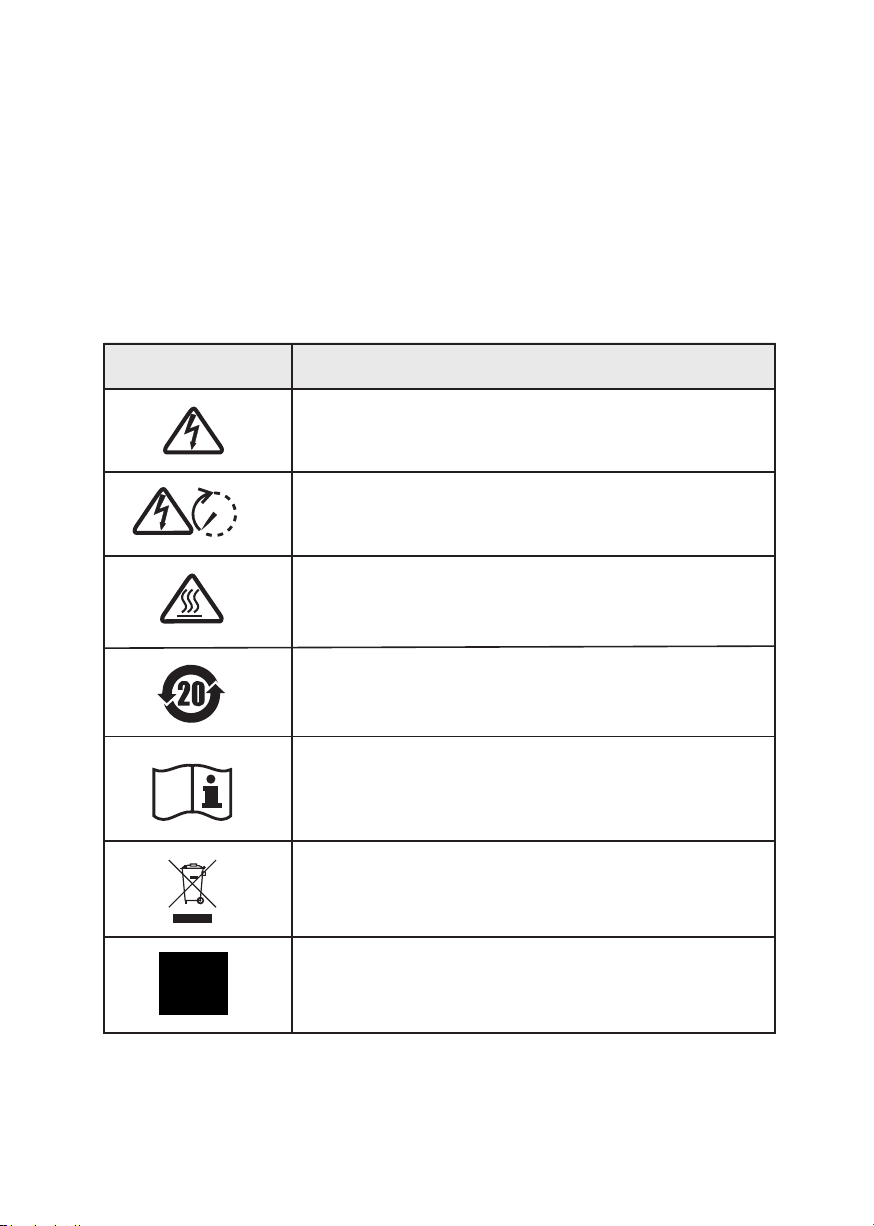
1.1 Symbols Used
6 Power2SA Inverter User Manual
Danger of high voltage and electric shock!
Only qualified personnel may perform work on the inverter.
Grounding terminal
Safety Symbol Description
Residual voltage exists after the inverter is powered off. It takes
5 minutes for system to discharge to a safe voltage.
Danger of hot surface
Product should not be disposed as household waste.
5 mins
Environmental Protection Use Period
Refer to the operating instructions

Safety
Power2SA Inverter User Manual 7
1.2 Safety Precaution
Installation, maintenance and connection of inverters must be performed by qualified personnel, in
compliance with local electrical standards, wiring rules and requirements of local power authorities and/
or companies.
The temperature of some parts of the inverter may exceed 60℃ during operation. Do not touch the
inverter during operation to avoid being burnt.
Ensure children are kept away from inverters.
Don’t open the front cover of the inverter. Apart from performing work at the wiring terminal (as
instructed in this manual), touching or changing components without authorization may cause injury
to people, damage to inverters and annulment of the warranty.
Static electricity may damage electronic components.Appropriate methods must be adopted to prevent
such damage to the inverter; otherwise the inverter may be damaged and the warranty annulled.
Ensure the output voltage of the proposed PV array is lower than the maximum rated input voltage of
the inverter; otherwise the inverter may be damaged and the warranty annulled.
When exposed to sunlight, the PV array generates dangerous high DC voltage. Please operate according
to our instructions, or it will result in danger to life.
PV modules should have an IEC61730 classArating.
If the equipment is used in a manner not specified by the manufacturer, the protection provided by the
equipment may be impaired.
Completely isolate the inverter before maintaining. Completely isolate the inverter should: switch off
the PV switch, disconnect the PV terminal, disconnect the battery terminal, and disconnect the AC
terminal.
Prohibit inserting or pulling the AC and DC terminals when the inverter is running.
In Australia, the inverter internal switching does not maintain the neutral neutral continuity. And neutral
integrity must be addressed by external connection arrangements.
Don’t connect Three phase hybrid inverter in the following ways:
BACKUP Port should not be connected to grid;
The single PV panel string should not be connected to two or more inverters.
After the inverter is powered off, the remaining electricity and heat may still cause electric shock and body
burns. Do not touch parts of inverter for 10 minutes after disconnection from the power sources.
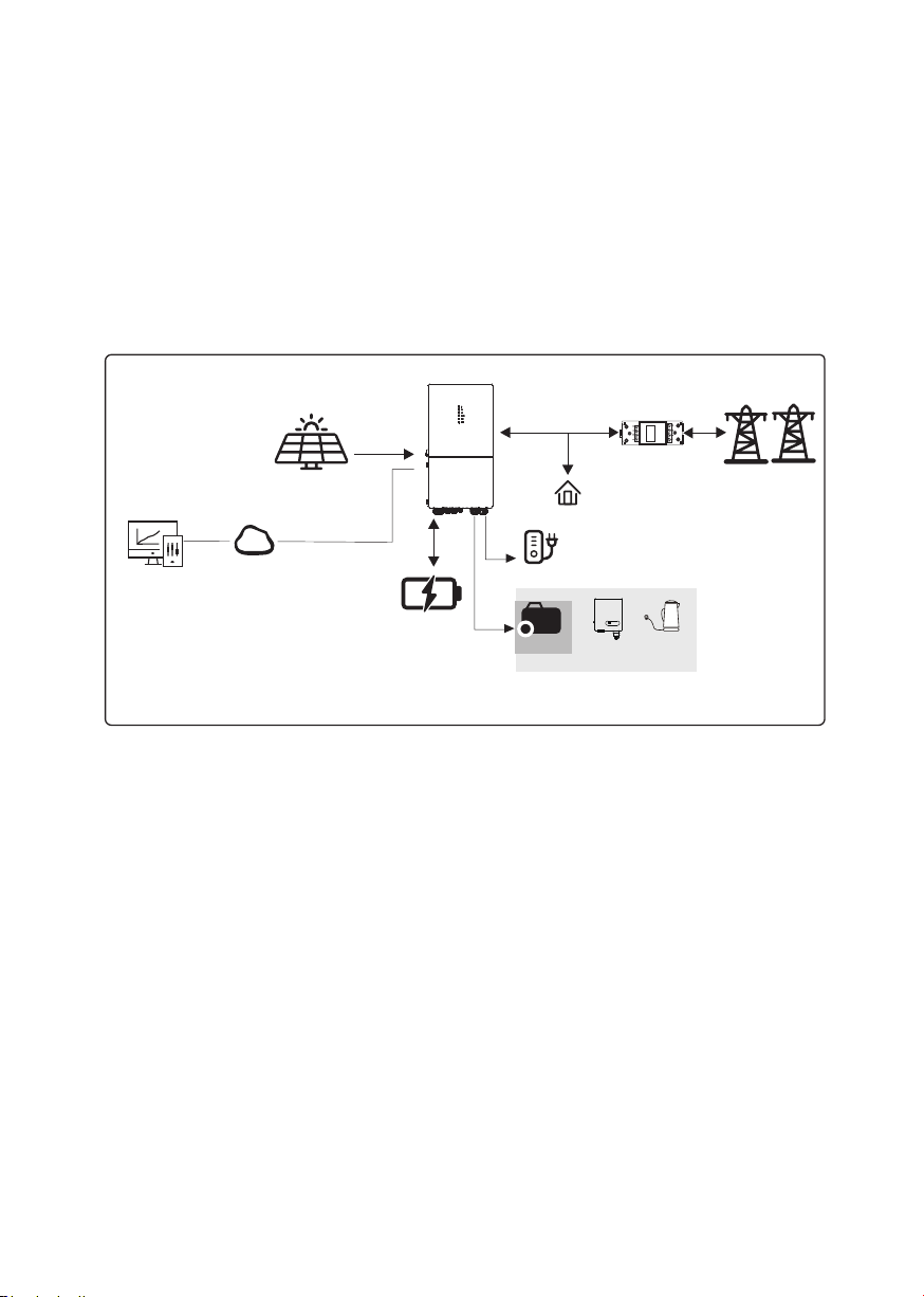
Monitoring
Device
Cloud
PVArray
P2SA Inverter
Sensor
Grid
P2SA Inverter Application System
Battery
Product Introduction
2. Product Introduction
2.1 Overview
Power2SA Inverter
The Power2SA inverter is a high-quality inverter which can convert solar energy to AC energy and store
energy into battery. Typically, a Power2SA inverter system consists of PV array, ESS inverter, battery,
loads and electricity sensor.
The energy generated by inverter can be preferentially supplied to its self-consumption, stored in the battery
for future use or fed into public grid.
Normal Load
8 Power2SA Inverter User Manual
BACKUP
Smart
Load
On-Grid
Inverter
Generator
or
or
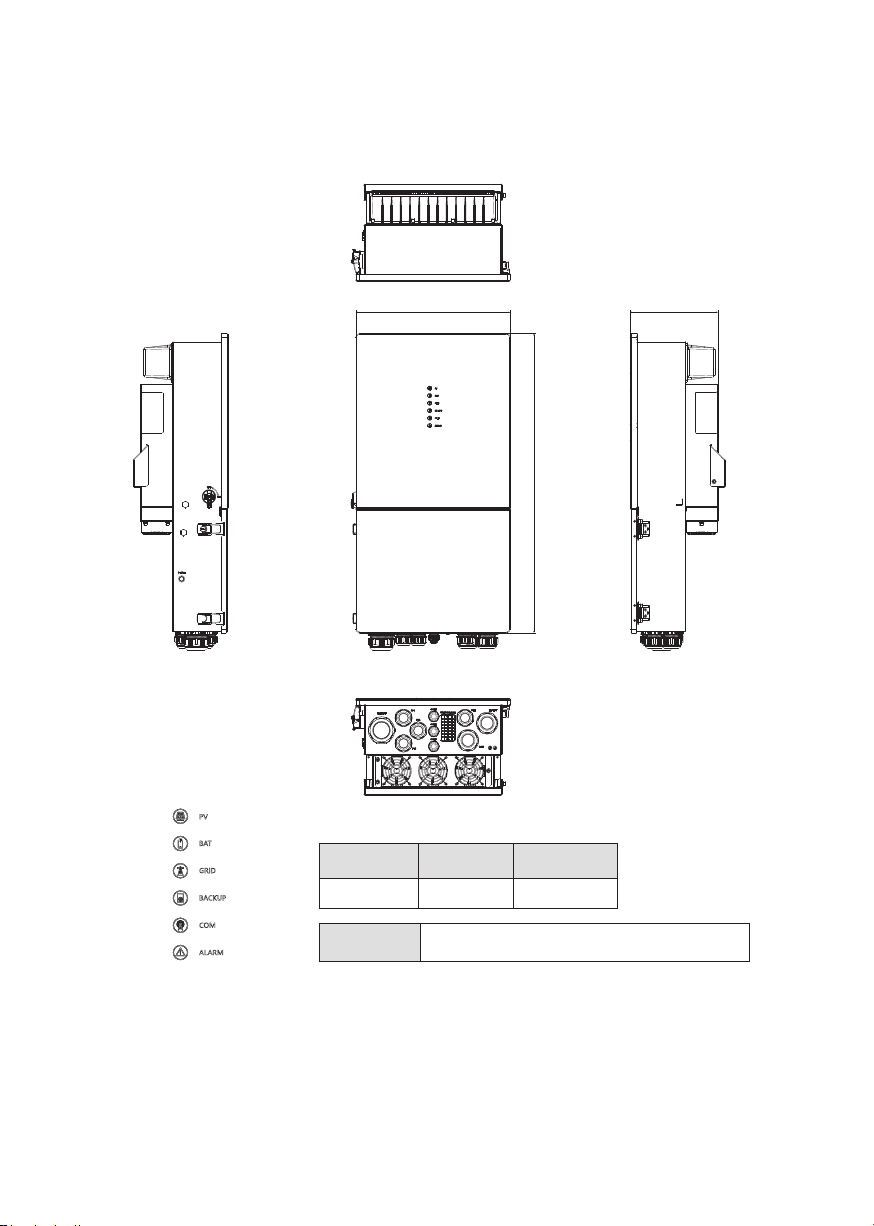
The External View of Power2SA Inverter
2.2 Product Appearance
LED Details
Width(mm) Depth(mm)
420 800 240
LED Indicators PV BAT GRID BACKUP COM ALARM
Product Introduction
Height(mm)
Power2SA Inverter User Manual 9
420.0
800.0
240.0
Product Introduction
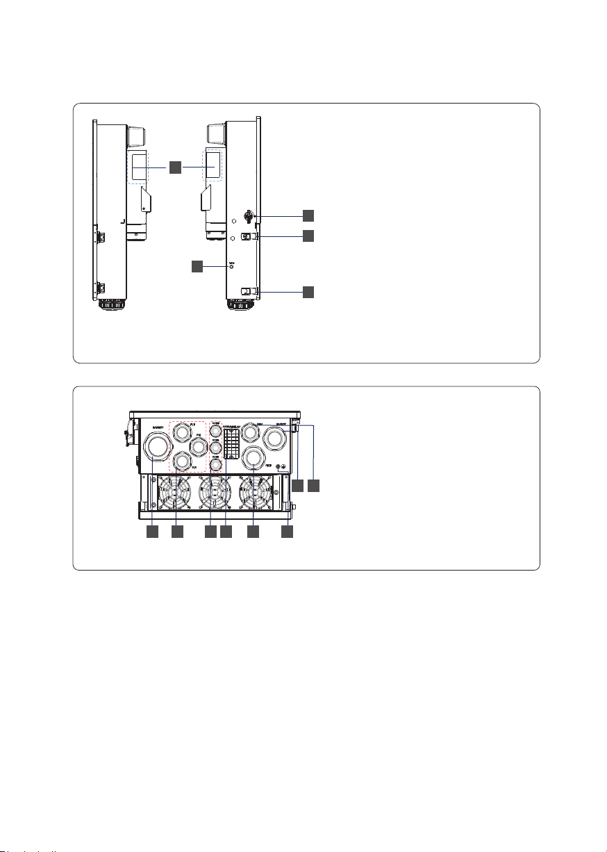
10 Power2SA Inverter User Manual
1. Battery Connect Terminals
2. PV Input Terminals
3. COM1/2/3 Ports (RS485, BMS,
DRM, CT, DRY, RSD, PARA)
4. COM Port (GPRS/WIFI/LAN)
5. GRID Output Terminal
6. Grounding Terminal
7. BACKUP Terminal
8. GEN Terminal
The Bottom View of Power2SA inverter
346
5
8
12
7
1. PV Switch
2. Toggle Latch ( for opening/closing
the junction box cover)
3. ON/OFF Button
4. Handle Areas
(right) (left)
The Side Views of Power2SA Inverter
4
1
2
2
3
Questo manuale è adatto per i seguenti modelli
1
Indice


