
Powerfix Profi PBMP 30 A1 Manuale utente

DRILL PUMP PBMP 30 A1
DRILL PUMP
Operating instructions
POMPĂ PENTRU MAŞINA DE
GĂURIT
Instrucţiuni de utilizare
PUMPA ZA BUŠILICU
Upute za upotrebu
IAN 86584
BOHRMASCHINENPUMPE
Bedienungsanleitung
ΑΝΤΛΙΑ ΗΛΕΚΤΡΙΚΟΥ
ΤΡΥΠΑΝΙΟΥ
Οδηүίες χρήσης

GB/CY Operating instructions Page 1
HR Upute za upotrebu Stranica 11
RO Instrucţiuni de utilizare Pagina 21
GR/CY Οδηүίες χρήσης Σελίδα 31
DE/AT/CH Bedienungsanleitung Seite 41
Before reading, unfold the page containing the illustrations and familiarise
yourself with all functions of the device.
Prije nego što pročitate tekst, otvorite stranicu sa slikama i upoznajte se na
osnovu toga sa svim funkcijama uređaja.
Înainte de a citi instrucţiunile, priviţi imaginile şi familiarizaţi-vă cu toate funcţiile
aparatului.
Πριν ξεκινήσετε την ανάγνωση, ανοίξτε τη σελίδα με τις εικόνες και εξοικει-
ωθείτε με όλες τις λειτουργίες της συσκευής.
Klappen Sie vor dem Lesen die Seite mit den Abbildungen aus und machen
Sie sich anschließend mit allen Funktionen des Gerätes vertraut.
A
B

- 1 -
GB/CY
CONTENT PAGE
Introduction 2
Safety instructions 2
Intended Usage 3
Technical Data 3
Items supplied 4
Overview of the appliance 4
Assembly material required 4
Assembly and connection 5
Disassembly of the drive shaft 7
Utilisation 8
Cleaning and care 8
Disposal 9
Declaration of conformity 9
Importer 9
Warranty and Service 10
IB_86584_PBMP30A1_LB7.qxd 05.12.2012 16:43 Uhr Seite 1

- 2 -
Introduction
Congratulations!
With your purchase you have decided in favour of a quality product. Familiarise
yourself with the product before taking it into use. To do this, read the following
operating instructions attentively. Use the product only as described and only
for the specified areas of application. Retain these instructions for future refe-
rence. In addition, pass these documents on, together with the product, to any
future owner.
Safety instructions
To avoid the risk of accidents and damage to the
appliance:
• Operate the pump ONLY when it is secured by the supplied mounting
against jolting, twisting and canting.
• Check the pump for a faultfree condition before ever taking it into use.
The pump may not be used if it shows signs of damage.
The drive shaft of the pump does not allow itself to be turned by hand.
This does not indicate that the pump is defective.
• Use only hoses certified as being able to withstand a pressure of at least
3 bars (44 psi).
• Check the plug-in connectors on the hoses for firm seating.
• Take steps to ensure that the fluid being pumped cannot come into contact
with the electric drill during pumping. Should it nonetheless occur, imme-
diately remove the power plug.
• Avoid the intake of coarse dirt, otherwise the pump could be damaged.
If needs be, use a filter on the suction hose.
GB/CY
IB_86584_PBMP30A1_LB7.qxd 05.12.2012 16:43 Uhr Seite 2

- 3 -
GB/CY
• This appliance is not intended for use by children or other individuals whose
physical, sensorial or intellectual abilities prevent safe usage of the appli-
ance should they not receive support or supervision in the correct operati-
on of the appliance. Children should be supervised to ensure that they do
not play with the appliance.
Intended Usage
This pump is intended for ...
– standard commercial right/left rotating electric drills with a 43 mm Euro-
spindle and a gear-wheel rim chuck/quick-release chuck or drill chuck
with SDS fitting, up to rotation speed of 3400 rpm,
– the pumping of cold or up to 40°C warm fluids, such as non-potable or
dirty water from fish tanks or ponds.
This pump is NNOOTTintended for ...
– the pumping of flammable, explosive, poisonous or caustic liquids or
foodstuffs.
– for industrial or commercial applications.
Technical Data
Capacity: max. 2,4 m3/h
Hose connection: 3/4” (19 mm)
Pressure: max. 3 bar
Delivery height: max. 30 m
Suction height: max. 3 m
Temperature of the fluid being pumped: max. 40°C
Dry run time: max. 12 seconds
Rotation speed: max. 3400 rpm
IB_86584_PBMP30A1_LB7.qxd 05.12.2012 16:43 Uhr Seite 3

- 4 -
Items supplied
- Pump
- Short drive shaft
- Long drive shaft
- Clamp fixing
- Mounting
- Open-ended spanner
- Storage box for the drive shafts and open-ended spanner
- This operating manual
Overview of the appliance
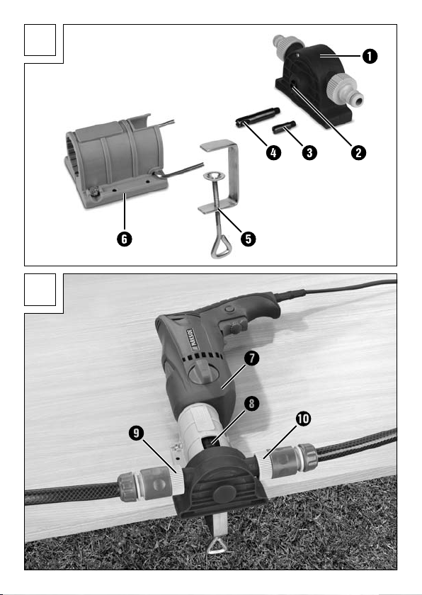
Figure A:
qPump
wDrive shaft of the pump
eShort drive shaft (suitable for gear-wheel/quick-release chuck)
rLong drive shaft (suitable for a drill chuck with SDS fitting)
tClamp fastening
yMounting
Figure B:
uElectric drill (not supplied)
iRecess for chuck key
oConnection for suction hose
aConnection for pressure hose
Assembly material required
- Philips-type screwdriver
- Flat-headed screwdriver
- Open-ended spanner (supplied)
GB/CY
IB_86584_PBMP30A1_LB7.qxd 05.12.2012 16:43 Uhr Seite 4

- 5 -
GB/CY
Assembly and connection
Assemble the mounting ywith the clamp fastening tonto a work surface,
as shown in figure B.
Alternatively, the mounting ycan also be secured to a work surface
with screws (assembly material not supplied).
When using a gear-wheel chuck and the short drive
shaft e...
Screw the short drive shaft eonto the drive shaft wof the pump q.
Insert the electric drill uwith the chuck into the mounting y.
Now push the pump qonto the mounting yso that the drive shaft e
projects into the chuck and the pins of the mounting yare located in the
reception holes on the pump q.
Now tighten the chuck with the chuck key through the recess iso firmly
that the pump qcan no longer release itself from the mounting y.
Tighten the cross-headed screw on the mounting yfirmly, so that the drill
ucannot jolt around.
Attach the suction hose to the connection oand the pressure hose to the
connection a. Pay heed to the direction of flow detailed on the
pump q.
When using a quick-release chuck and the short drive
shaft e...
Secure the short drive shaft einto the chuck.
Insert the electric drill u, with the pre-assembled drive shaft ein the
chuck, into the mounting y.
Securely tighten the cross-head screw on the mounting yso that the drill u
is being firmly held.
IB_86584_PBMP30A1_LB7.qxd 05.12.2012 16:43 Uhr Seite 5

- 6 -
Now push the pump qonto the mounting yso that the drive shaft e
projects into the thread of the drive shaft w, and the pins of the mounting
yare located in the reception holes on the pump q.
Let the drill ustart to run in a clockwise rotation and at low revolutions
and then guide the pump qstraight onto the drive shaft e. The drive
shaft eis thereby secured to the pump q.
Attach the suction hose to the connection oand the pressure hose to the
connection a. Pay heed to the direction of flow detailed on the
pump q.
When using a chuck with SDS fitting and the long drive
shaft r...
Attach the long drive shaft rinto the chuck.
Insert the electric drill u, with the pre-assembled drive shaft rin the
chuck, into the mounting y.
Tighten the cross-headed screw on the mounting yfirmly, so that the drill u
cannot jolt around.
Now push the pump qonto the mounting yso that the drive shaft r
projects into the thread of the drive shaft wand the pins of the mounting
yare located in the reception holes on the pump q.
Allow the electric drill uto run with a clockwise rotation and low revoluti-
ons and guide the pump qstraight on to the drive shaft r. With this the
drive shaft rwill be fixated onto the pump q.
Attach the suction hose to the connection oand the pressure hose to the
connection a. Pay heed to the direction of flow detailed on the
pump q.
GB/CY
IB_86584_PBMP30A1_LB7.qxd 05.12.2012 16:43 Uhr Seite 6

- 7 -
GB/CY
Disassembly of the drive shaft
Disassembly of the short drive shaft e
Wheel rim chuck
Open the chuck with the chuck key through the recess iand then remove
the pump qfrom the mounting y.
Unscrew the short drive shaft eby using a cross-headed screwdriver and
the open-ended spanner from the pump q.
Quick-release chuck
Using the open-ended spanner through the recess i, counter screw the
drive shaft wof the pump q.
Allow the electric drill uto run with an anti-clockwise rotation and low re-
volutions. The drive shaft eis thereby released from the pump q.
Remove the pump qfrom the mounting y.
Remove the drive shaft efrom the chuck.
Disassembly of the long drive shaft r
Chuck with SDS fitting
Using the open-ended spanner through the recess, icounter screw the
drive shaft wof the pump q.
Allow the electric drill uto run with an anti-clockwise rotation and low
revolutions. With this the drive shaft rwill be released from the pump q.
Remove the pump qfrom the mounting y.
Remove the drive shaft rfrom the chuck.
IB_86584_PBMP30A1_LB7.qxd 05.12.2012 16:43 Uhr Seite 7
Altri manuali per PBMP 30 A1
1
Indice
Lingue:
Altri manuali Powerfix Profi Pompa dell'acqua


Manuali Pompa dell'acqua popolari di altre marche


Sykes AmeriPumps
Sykes AmeriPumps GP100M Guida alla risoluzione dei problemi

DUROMAX
DUROMAX XP WX Series Manuale utente

BRINKMANN PUMPS
BRINKMANN PUMPS SBF550 Manuale utente

Franklin Electric
Franklin Electric IPS Manuale utente

Xylem
Xylem e-1532 Series Manuale utente

Milton Roy
Milton Roy PRIMEROYAL Manuale utente