Prexiso PLR50 Manuale utente
www.prexiso-eu.com
PDF
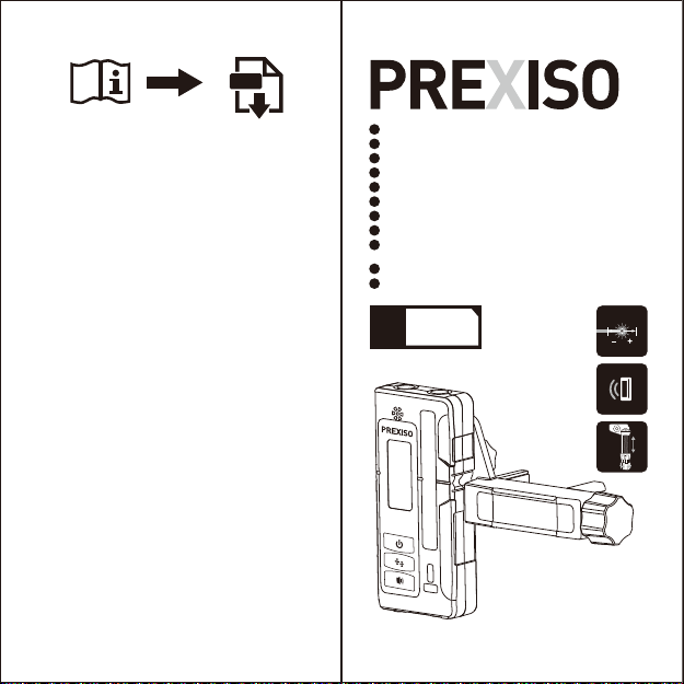
PLR50
www.prexiso-eu.com
WARRANTY
LIMITED
YEARS
2
LINE LASER RECEIVER FOR RED & GREEN BEAM
LINIENLASEREMPFÄNGER FÜR ROT & GRÜN BEAM
LIGNE LASER RÉCEPTEUR POUR FAISCEAU ROUGE ET VERT
RICEVITORE LASER DI LINEA PER ROSSO E RAGGIO VERDE
RECEPTOR LÁSER DE LÍNEA PARA HAZ ROJO Y VERDE
LIJN LASER ONTVANGER VOOR ROOD EN GROEN BEAM
KIRMIZI VE YEŞIL IŞIN IÇIN ÇIZGI LAZER ALICISI
LINE LASER MODTAGER TIL RØD OG GRØN STRÅLE
LINEAARINEN LASERVASTAANOTIN PUNAISILLE JA
VIHREILLE PALKKEILLE
LASERMOTTAKEREN LINJE FOR RØD OG GRØNN STRÅLE
LINIOWY ODBIORNIK LASEROWY Z WIĄZKĄ CZERWONĄ I ZIELONĄ
EN
DE
FR
IT
ES
NL
TR
DK
FI
NO
PL
±1mm
±1/32"
≥300 m
≥ 1000 ft
Prexiso AG
Fabrikstrasse 1
CH-8586 Erlen / Switzerland

IMPORTANT:
Read before Using EN
AREAS OF RESPONSIBILITY
RESPONSIBILITIES OF THE PERSON IN CHARGE OF
THE INSTRUMENT:
• To understand the safety instructions on the
product and the instructions in the User Manual.
• To be familiar with local safety regulations
relating to accident prevention.
• Always prevent from accessing to the product by
unauthorized personnel.
FUNCTION
The detector is intended for swift finding of
pulsating laser beams.
PRODUCT OVERVIEW
The safety instructions and the user manual
should be read through carefully before the
product is used for the first time.
1.Keep the instrument dry.
2.Keep the instrument and battery out of reach of infants
and children.
3.Keep the detector away from magnetic data medium and
magnetically-sensitive equipment. The effect of the
magnets can lead to irreversible data loss.
4.When the symbol “ ” appears, the batteries are low
and should be replaced. Ensure that battery polarity
connections are correct when replacing batteries. If
you are not using the instrument for a long time, remove
the battery.
Ensure that battery polarity connections are correct
when replacing batteries. If you are not using the
instrument for a long time, remove the battery.
SAFETY INSTRUCTION:
CAUTION
PROHIBITED USE
• Using the product without instruction.
• Using outside the stated limits.
• Deactivation of safety systems and removal of explanatory
and hazard labels.
• Opening of the equipment by using tools
(screwdrivers, etc.).
• Carrying out modification or conversion of the product.
• Use of accessories from other manufacturers without
express approval.
• Deliberate dazzling of third parties; also in the dark.
• Inadequate safeguards at the surveying site (e.g. when
measuring on roads, construction sites, etc.).
• Deliberate or irresponsible behavior on scaffolding, when
using ladders, when measuring near machines which are
running or near parts of machines or installations which are
unprotected.
LIMITS OF USE
i
Never attempt to repair the product yourself. In case of
damage, contact a local dealer.
Refer to section "Technical data".The device is designed
for use in areas ently habitable by humans. Do not use
the product in explosion hazardous areas or in aggressive
environments.
Made in China
Ser.NO.:
(1)
(2)
(3)
(4)
(5)
(6)
(7)
(15)
(8)
(9)
(10)
(11)
(12)
(14)
(13)
(7)
(7)
1.Speaker
2.LCD Display(Front)
3.Power On/Off Illumination On/Off
4.Selecting the detecting
accuracy button
5.Audio signal button
6.Reception area for the laser beam
7.Centre mark
8.Bubble vial
9.Bubble vial
10.Guide hole for holder
11.1/4"-20 screw
12.Guide hole for holder
13.Battery compartment
14.LCD Display(Back)
15.Magnet
1 2

OPERATION INSTRUCTIONS
1. Inserting/Replacing the batteries
Open Battery compartment and insert two AA batteries in
the battery compartment (AA alkaline batteries are
recommended for the detecting tool.).
When inserting batteries, pay attention to the correct
polarity according to the representation on the inside of the
battery compartment.
NOTE: Remove the batteries from the detector when not
using it for extended periods. When storing for extended
periods, the batteries can corrode and discharge
themselves.
2. Setting up the detector
Switch on the pulse function of the line laser. Select an
operating mode on the line laser where either only one
horizontal or vertical laser plane is generated.
Position the detector in such a manner that the laser beam
can reach the reception area 6. Align the detector in such a
manner that the laser beam runs laterally through the
reception area (as shown in the figure).
3. Switching On and Off
A loud audio signal sounds when switching on the detector
and the detector receives the laser beam from the line
laser. Therefore, keep the detector away from your ear or
other persons when switching on. The loud audio signal can
cause hearing defects.
Press the On/Off button 3 to switch on the detector. When
the detector is turned on, all the indicators are displayed,
and press the On/Off button again to turn On/Off the LEDs
lights.
After switching on the detector, a medium volume and the “
high” accuracy is always set.
To switch off the detector, continuously press the On/Off
button 3 for about three seconds.
Notes: If no button on the detector is pressed and no laser
beam reaches the reception area 6 for 30minutes, the
detector automatically turns off. If no button on the detector
is pressed and no laser beam reaches the reception area 6
for 10minutes, the LED light of the detector automatically
turns off.
4. Selecting the Setting of the Centre Indictor
With button 4, you can specify with which accuracy the
position of the laser beam is indicated as central on the
reception area:
-“ High” adjustment (indication in the a area on the
display)
-“Low” adjustment (indication in the a area on the
display)
5. Direction Indicators
The position of the laser beam in the reception area 6 is
indicated:
-
-+
+
a
b
f
e
d
cDISPLAY
a.Indicator for detecting accuracy
b.Battery indicator
c.Audio signal indicator
d.Direction indicator
“ move downward”
e.Centre indicator
f.Direction indicator
“move upward”
3 4

(1)
(2)
(3)
(4)
(5)
(4)
(2)
-By the direction indicators “move downward” d, “move
upward” for centre e on the display 2 on the front and back
of the detector.
-Optionally by the audio signal (see the following No. 6
“Audio Signal for Indication of the Laser Beam”
operation instruction).
Detector too low: If the laser beam runs through the upper
half of the reception area 6, then the direction indicator f on
the display. If the audio signal is switched on, a signal
sounds at high frequency.
Detector too high: If the laser beam runs through the lower
half of the reception area 6, then the direction indicator d on
the display. If the audio signal is switched on, a signal
sounds at low frequency.
Move the detector downward in the arrow direction.
Detector in centre position: When the laser beam runs
through the reception area 6 at the centre mark 7, the
centre indicator e on the display. When the audio signal is
switched on, a continuous signal sounds.
6.Audio Signal for Indication of the Laser Beam
The position of the laser beam on the reception area 6 can
be indicated via an audio signal. After switching on the
detector, the audio signal is always set to high volume. The
volume level can be decreased or switched off.
To change the volume level or switch off the audio signal,
push the Audio signal button 5 until the requested volume
level is indicated on the display. At low volume level, the
audio signal indicator c appears on the display with
no bar .
At high volume level, the audio signal indicator c appears
on the display with two bars . When the audio signal is
set to off, the indicator goes out. Independent of the audio
signal setting, a short beep sounds at low volume level
every time when a button is pressed on the detector.
7.Indicators and lighting of the back display
The indicators and lighting of the back display are switched
On/Off simultaneously when the indicators and lighting of
the front display are switched On/Off.
8. Working Advice
Marking
When the laser beam runs through the center of the
reception area 6, its height can be marked at the centre
mark 7 right and left on the detector.
When marking, take care to align the defector exactly
vertical ( for horizontal laser beam), or horizontal
(for vertical laser beam) by making use of the bubble vials 8
& 9 .
Rod Clamp Installation
The Detector can be used in hand or with an optional clamp
to install the detector to a measuring rod, pole or similar
object.
To install the clamp on the detector (See figure):
• Guide the clamp towards the detector by using the
alignment hole.
• Tighten the fixing screw.
(1) Alignment Points-help secure and align rod clamp.
(2) Captive Rod Clamp Screw-attaches to the back of
detector.
(3) Alignment Points-help secure and align rod clamp.
(4) Reversible Face-slanted face for round and oval rods;
flat face for rectangular and square rods.
(5) Clamping Screw Knob-secures clamp to rods by moving
the traveling jaw. Clockwise tightens; Counter clockwise
loosens.
9. Technical Data
Laser Detector
Measuring accuracy(High)
Measuring accuracy(High)
Working range
Laser reception window width
Bubble vial accuracy
Operating time
Auto power off(with no signal detected)
Batteries
Operating temperature
Storage temperature
Degree of protection
PLR50
±1mm
±2mm
50m
80mm
30’/2mm
≥24h
30min
2 x 1.5V alkaline AA
-10ºC…+50ºC
-20ºC…+70ºC
IP54
5 6

10. DISPOSAL
CAUTION
WARNING:
Flat batteries must not be disposed of with household
waste. Care for the environ-ment and take them to the
collection points provided in accordance with national or
local regulations. The product must not be disposed with
household waste. Dispose of the product appropri-ately in
accordance with the national regulations in force in your
country.
Adhere to the national and country specific
regulations.Product specific treatment and waste
management can be downloaded from our homepage.
Electromagnetic Compatibility
(EMC)
The device conforms to the most stringent requirements of
the relevant standards and regulations. However, the
possibility of causing inter-ference in other devices cannot
be totally excluded.
11. WARRANTY
The Prexiso PLR50 has a two-year warranty. For further
information on this, contact your dealer. This warranty is
void if product is used for commercial purposes. This
warranty is not transferable and does not cover products
damaged by misuse, neglect,
accident, alterations or use and maintenance other than
that specified in the owner's manual. This warranty does not
apply to any expendable parts that can wear from normal
use. This warranty excludes any accessories.
www.prexiso-eu.com
Prexiso AG
Fabrikstrasse 1
CH-8586 Erlen / Switzerland
7 8
Indice
Altri manuali Prexiso Sensore di sicurezza


