Pride GUARDIAN II Manuale utente

Pride Engineering, LLC | 10301 Xylon Ave. N., Suite 100 | Minneapolis, MN 55445
www.pridecan.com
GUARDIAN II
BODYMAKER OVER TRAVEL GAUGE
USER’S MANUAL
English Version 5.0 | Original Instructions | Date of Issue: March 15, 2021

1
Pride Engineering, LLC •10301 Xylon Ave. N. Suite 100 Minneapolis, MN 55445 USA •Phone: +1 (763) 427-6250 •www.pridecan.com
1. Introduction to Equipment and Safety
1.1 INTRODUCTION TO USER’S MANUAL
The purpose of this manual is to provide initial set-up, operational, part identification,
and maintenance information for Pride’s Guardian II Over Travel Monitoring and
Control System. Pride Engineering, LLC, Minneapolis, Minnesota +1 (763) 427-6250
should be consulted prior to major field repairs.
READ MANUAL THOROUGHLY BEFORE
INSTALLING OR OPERATING EQUIPMENT
The User’s Manual is intended to help familiarize the user with the safe and
effective operation of Pride’s Guardian II Monitoring and Control System.
Following the instructions in the manual will reduce safety risks while facilitating
the effective use of the equipment.
1.1.1 SAFETY RELATED SYMBOLS DEFINITIONS
Signifies read manual
Signifies general warning,
indicating danger to life and limb
or extensive machine damage
Signifies mandatory action
Signifies electrical hazard
Signifies important information

2
Pride Engineering, LLC •10301 Xylon Ave. N. Suite 100 Minneapolis, MN 55445 USA •Phone: +1 (763) 427-6250 •www.pridecan.com
1.2 TECHNICAL CHARACTERISTICS
1.2.1 INTENDED USE
The Pride Engineering Guardian II is intended to be used to measure and
report bodymaker over travel amounts.
1.2.2 MODIFICATION OF EQUIPMENT
Do not modify the equipment. Modification of the equipment may defeat
measures taken to ensure safe operation of the equipment.
1.2.3 TECHNICAL CHARACTERISTICS
• Weight: 13.2 lbs. (6 kg)
• Height: 6.7 inches (17 cm)
• Length: 9.5 inches (24 cm)
• Width: 11.4 inches (29 cm)
• Operating Conditions:
– Air Temperature: 60 F – 120 F (15 C – 50 C)
– Relative Humidity: 35 – 85 % Non-condensating
– Altitude: 0 – 10,000 feet (0 – 3,000 m)
• Ingress Protection Level: IP65
• Equipment requires a source of 24V DC power, 3 amps.
1.3 SAFETY
1.3.1 PROPER USE FOR INTENDED PURPOSE
1.3.1.1
This equipment is intended for use in conjunction with Pride Engineering’s bottom
former when used in can bodymaking equipment in an indoor environment.
1.3.1.2
You can contact Pride Engineering, LLC for technical assistance at:
Pride Engineering, LLC
10301 Xylon Ave. N
Minneapolis, MN 55445 USA
+1 (763) 427-6250

3
Pride Engineering, LLC •10301 Xylon Ave. N. Suite 100 Minneapolis, MN 55445 USA •Phone: +1 (763) 427-6250 •www.pridecan.com
1.3.2 IMPROPER USE
1.3.2.1
The following are improper, prohibited uses of the equipment:
• Using the equipment with the case open.
• Using the equipment with the name plate or warning labels removed or illegible.
• Connecting the equipment to a power source that does not meet the specifica-
tions for the equipment.
• Using the equipment while wired differently than as directed.
• Using the equipment with any sensor other than the sensor specified by
Pride Engineering for the equipment.
• Working on or trying to mount the sensor while the bodymaker is operating.
1.3.3 USER SAFETY
Operators of the equipment should ensure they are following the safety proce-
dures for the environment for which the equipment is installed. Operator’s and
maintenance personnel should read the user’s manual prior to installation and
use of the equipment. Only trained maintenance personnel should gain access
to the inside of the case.
1.3.4 NOISE MEASUREMENT
Noise produced by this equipment is less than 70 db(A). However, this equip-
ment is usually installed in an environment that requires hearing protection.
Follow the requirements for the facility where the equipment is installed.

4
Pride Engineering, LLC •10301 Xylon Ave. N. Suite 100 Minneapolis, MN 55445 USA •Phone: +1 (763) 427-6250 •www.pridecan.com
2. Installation and Preparation for Use
1
2
Mount the Guardian II in a location that provides access by the operator
and facilitates wiring by the electrician to the bodymaker control.
From Bodymaker
Control PLC
From Sensor on Domer
(Via Junction Box)
Sensor Junction Box
The safety of any system incorporating the Guardian II
product is the responsibility of the assembler of the system.
Make sure bodymaker is stopped before installing sensor on the bottom former.
Mount the sensor junction box
to allow the sensor to be routed
between the domer and the
Guardian II.

5
Pride Engineering, LLC •10301 Xylon Ave. N. Suite 100 Minneapolis, MN 55445 USA •Phone: +1 (763) 427-6250 •www.pridecan.com
3Connect wires from Bodymaker PLC to Guardian II
and Guardian II to the Sensor as shown below.
Sensor Output
+24 VDC
+24 VDC Common
Brown
Blue
Black
To TB 24VCOM
To TB 24VDC
To PLC Supply 24 VDC
From PLC Remote Reset
From PLC Machine Running
To PLC Upper Limit Input
To PLC Lower Limit Input
To PLC Supply Common
Circuit Breaker.
Green Means
Open and Red
Means Closed.

Pride Engineering, LLC •10301 Xylon Ave. N. Suite 100 Minneapolis, MN 55445 USA •Phone: +1 (763) 427-6250 •www.pridecan.com
4
5
6
Install the sensor bracket, with Sensor and wire attached, to the bottom
former with two ¼ --28 screws, 0.250” long. Do not torque them yet
because they must be loose to set the sensor gap in the next step below.
Set the distance between the sensor and the Outer Housing flange. Use a 0.025” (0.635
mm) thick feeler gauge to set the gap as accurately as possible. The size of the gap is very
important because the gap directly effects the strength of the signal from the sensor.
The Guardian interprets the strength of the signal to determine value of the over travel.
Once the gap is set, torque both screws to 20 lb.-ft or 27 N·m. Re-check the gap to be
certain that the sensor did not move while the screws were being tightened. The 0.025”
(0.635 mm) gap should be maintained.
• Select
• Select for over travel setup page
• Test sensor connection by selecting
• Black bar should be in green zone, adjust sensor position as needed
Setting Gap 0.025"
(.635 mm)
(2) 1/4 – 28 0.250" Long
Torque Bracket Mounting
Screws 20 lb.-ft. or
27 N·m

7
Pride Engineering, LLC •10301 Xylon Ave. N. Suite 100 Minneapolis, MN 55445 USA •Phone: +1 (763) 427-6250 •www.pridecan.com
7Secure cable to the rear of the bottom
former with the Hose Clamp provided.
WARNING: THE GUARDIAN CABLE MUST BE SECURED WITH THE
HOSE CLAMP TO THE BACK OF THE DOMER AT ALL TIMES OR THE
SENSOR/WIRING CONNECTION WILL BE DAMAGED.
Domer Air Supply
To Guardian
Control
Through
Junction Box
Hose Clamp –
Must be Secure
at all Times

8
Pride Engineering, LLC •10301 Xylon Ave. N. Suite 100 Minneapolis, MN 55445 USA •Phone: +1 (763) 427-6250 •www.pridecan.com
Supplied
cable
from over
travel
sensor
Supplied
cable to
Guardian
Crimp ring connector
onto sensor cable
assembly shield
and secure to
grounding lug.
Terminate wiring from
both cables as shown.
Black–Black
Brown–Brown
Blue–Blue
Terminate drain wire
to green terminal
as shown.
8
9
Connect wires from Sensor to Guardian II via the junction box as shown below.
When the wiring is complete,
the circuit breaker in the
Guardian II should be switched
to closed. This will start the
Guardian II computer and display.
9
Pride Engineering, LLC •10301 Xylon Ave. N. Suite 100 Minneapolis, MN 55445 USA •Phone: +1 (763) 427-6250 •www.pridecan.com
3. Operating Instructions
1
2
3
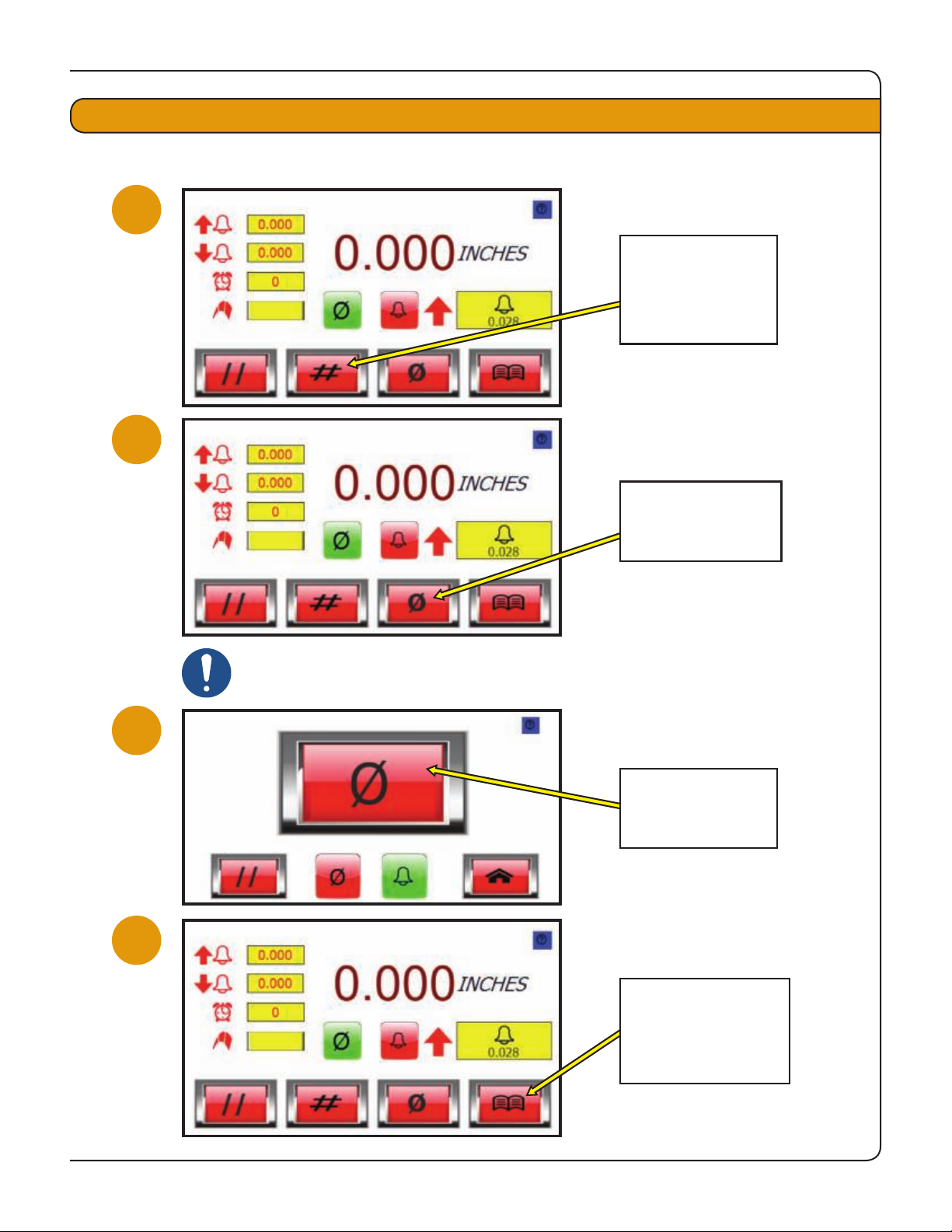
4
Select UNITS to
set the unit of
measure to either
mm or inches.
Select ZERO to
set the over travel
sensor to zero.
Press ZERO to set
the over travel
sensor to zero.
Select MENU to
set the LO LIMIT,
HI LIMIT and
DELAY parameters.
Bodymaker must be stopped
before setting zero.
Indice
Altri manuali Pride Controllori


