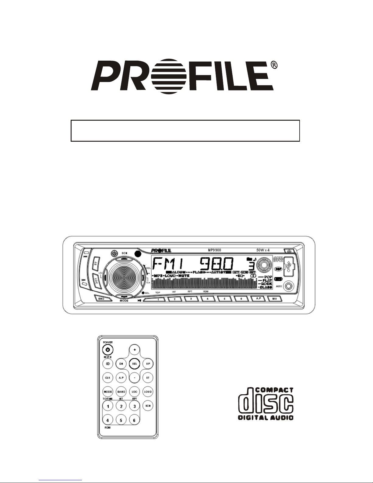
Profile MP9900 Guida rapida

AM/FM HIGH POWER FLIP DOWN DETACHABLE FACE
CD/USB/MMC/MP3 PLAYER
MP9900
INSTALLATION INSTRUCTIONS / OWNER S MANUAL
,

1
INTRODUCTION
Congratulations on your purchase of a Profile state-of-the-art single disc MP3/CD
and MMC/USB player. Your selection of a Profile car audio product indicates a true
appreciation of fine musical reproduction. Whether adding to an existing system or
including your Profile MP3/CD player in a new system, you are certain to notice
immediate performance benefits.
FEATURES
50W x 4 Power Output ESP (Electronic Shock Protection)
Dual RCA Line Outputs(Front & Rear)
ISO/DIN Mounting
Aux. Inputs (RCA & Front Jack)
Blinking Security L.E.D.
30 Station Memory
Full Electronic Function Controls
Disc Scan, Random & Repeat Play
KEEP YOUR SALES RECEIPT
Take this time to attach your sales receipt to the manual and put in a safe place.
In case of any reason this product may need warranty service, your receipt will
be necessary to establish purchase date.
IMPORTANT! Before making any connections, disconnect the car s battery
until the installation is completed to avoid possible damage to the electrical
system.
Serial # Purchase Date
,
Remote Control
Power Level Meter
4 Band Preset Equalizer
Clock
Loud Function
Flip Down Detachable Face MP3 Playback (USB & MMC Connections)

2
SAFETY PRECAUTIONS
Secure the CD player
When installing your CD player in the vehicle, make sure it is mounted properly in the dash,
using an after market installation kit if needed. When using the supplied mounting sleeve,
it is a must that you also use the supplied back brace to support the back of the CD
player.
Use caution when mounting the CD player.
Remember there are many electrical wires, vacuum lines, brake lines and air bag deployment
wires. Make sure you know where they are when mounting the CD player to avoid puncturing
lines, and shorting wires.
Use high grade wire connectors.
To ensure maximum power transfer and secure safe connections, it is recommended to use
high grade barrel or crimp cap connectors.
Do not run any wires underneath the vehicle.
Exposed wires can be cut or damaged. It is best to run all wires through the vehicle under the
carpet and/or side panels. This enables to a cleaner installation and less risk of damage.
Run signal wires away from electrical wires
To avoid possibility of induced noise from the car's electrical system (i.e. popping noises or
engine noise), run signal wires away from the car's electrical wiring.
Make all ground wires as short as possible and terminated at the same point.
In order to reduce the chance of ground loops (i.e. engine noise), make the grounded wire as
short as possible to reduce the wire's resistance. Also, when using multiple components, make
sure all units are grounded at the same point.
Avoid sharp edges when running the wires.
To avoid the possibility of power, signal or speaker shorts, be careful not to allow the amplifier
wires to come in contact with sharp edges. Use a grommet to protect the wire when running
through the fire wall .
.
MP9900

3
CARE AND MAINTENANCE
Cleaning the CD player
When cleaning the vehicle, be sure not to get any water in or on the CD player. Clean only
the exterior surface of the unit with a dry, clean soft towel using no chemical solvents.
Operating in extreme temperatures
Sometimes the unit will not operate in extreme, hot or cold temperatures. If this is the case,
wait until the temperature in the vehicle is normal, then resume operation.
Protect your CDs.
When not using the disc player, it is recommended that you remove the CD.
Do not leave an ejected disc sitting on the edge of the disc player for long periods of time.
The disc will warp under direct sunlight. Always put each disc in its case to protect them
during times of non-use.
CD operation.
Never attempt to force anything other than a compact disc in the disc slot. This disc player
is a precision instrument that could be damaged by a foreign object.
Disc skip
When driving down a very rough road, the disc may skip. This will not scratch or damage the disc.
Removing and protecting detachable face plate.
The face plate of the unit may be removed as a theft deterrent. After removing the face
plate, use the case provided to keep the face plate from getting damaged.
PROTECTIVE CASE
( FIG.2)
Press the OPEN button to flip down the face plate (Fig 1). Then hold the right side of the
face plate and pull it out from the unit (Fig.2)
Store the face plate in the protective case provided for safe keeping (Fig.3).
OPEN BUTTON
( FIG.1) ( FIG.3)
FACE PLATE
FACE PLATE

4
DISC CARE AND PLAY:
Before playing, clean the disc with a clean, lint-free cloth.
Wipe the disc in the direction of the arrow.
Do not use solvents such as benzine or thinners. Commercially available
cleaners or anti static spray will damage the unit.
Insert a disc with the labeled surface up.
Do not try to insert another disc when one has already been inserted.
Doing so may damage the unit.
Label
surface up
Handle the disc by its edge to keep the disc clean and do not touch
the surface.
Do not stick paper or tape on the disc.
Do not expose the disc to direct sunlight which can cause the disc to warp.
Always store the disc in its case for protection. Scratched up discs will
produce poor sound performance and cause CD player to skip.
MP9900

5
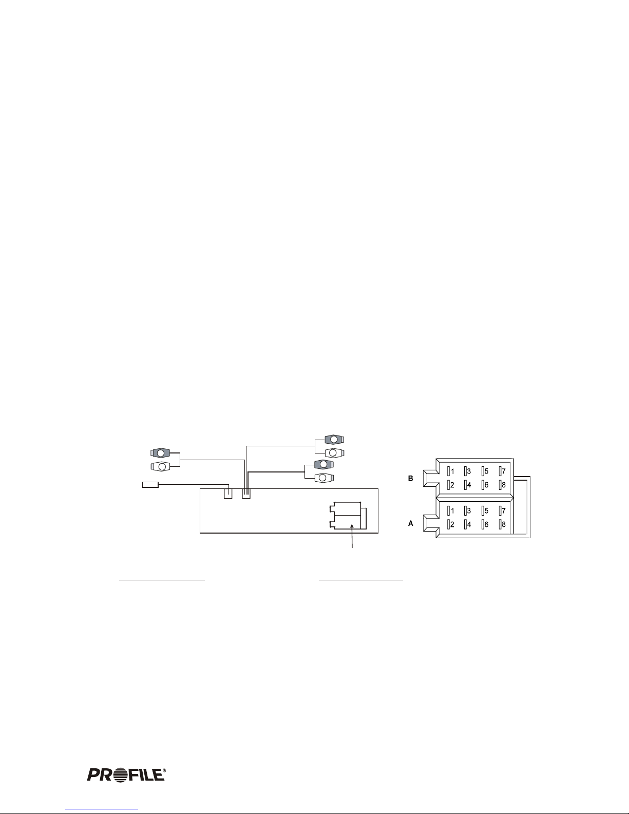
ELECTRICAL AND SIGNAL CONNECTIONS
FOUR SPEAKER SYSTEM
Before making the following connections, take time to look over the vehicle's wiring and
determine the location and wires you will be connecting to. If you do not wish to cut or tap
into the vehicles existing factory wiring, there are wiring kits available at your car audio
retailer that will allow you to plug directly into the factory wiring harness. Make sure to
test all wires before connecting to the CD Player.
!Connect Black wire to chassis ground.
!Connect the Yellow memory backup wire to a constant +12 volt power source wire.
!Connect the Red power wire to a switched +12 volt power source wire. (The power
wire that is energized when the key is in the accessory position).
!Blue wire is connected only if a power antenna or an amplifier is used in the
system. This wire supplies +12 volt output when the CD Player is turned on,
which activates most power antenna relays or amplifier turn on circuits.
CONNECTOR A
1.
2.
3.
4. Yellow - Memory +12V (15A)
5. Blue - Auto Antenna
6.
7. Red - Power B+ (Switched +12V)
8. Black - Ground
CONNECTOR B
1. Violet
2. Violet/Black
3. Gray
4. Gray/Black
5. White
6. White/Black
7. Green
8. Green/Black
FUSE 15 A
ISO SOCKET
REAR RCA LINE OUT
R CH RED
R CH RED
R CH RED L CH WHITE
L CH WHITE
L CH WHITE
GRAY
FRONT RCA LINE OUT
AUX RCA LINE IN
ANTENNA IN
BLACK
BROWN
R
L
R
R
L
L
Low level (RCA) signal output
for connection to amplifier or
signal processors.
Rear Right Speaker (+)
Rear Right Speaker (-)
Front Right Speaker (+)
Front Right Speaker (-)
Front Left Speaker (+)
Front Left Speaker (-)
Rear Left Speaker (+)
Rear Left Speaker (-)
ISO SOCKET

6MP9900
TWO SPEAKER SYSTEM
Low level (RCA) signal output
for connection to amplifier or
signal processors.
CAUTION! Tape unused wires so they do not short against other wires or
chassis ground.
CONNECTOR A
1.
2.
3.
4. Yellow - Memory +12V (15A)
5. Blue - Auto Antenna
6.
7. Red - Power B+ (Switched +12V)
8. Black - Ground
CONNECTOR B
1. Violet
2. Violet/Black
3. Gray
4. Gray/Black
5. White
6. White/Black
7. Green
8. Green/Black
FUSE 15 A
ISO SOCKET
REAR RCA LINE OUT
R CH RED
R CH RED
R CH RED L CH WHITE
L CH WHITE
L CH WHITE
GRAY
FRONT RCA LINE OUT
AUX RCA LINE IN
ANTENNA IN
BLACK
BROWN
R
L
R
R
L
L
- Not Used
- Not Used
Front Right Speaker (+)
Front Right Speaker (-)
Front Left Speaker (+)
Front Left Speaker (-)
- Not Used
- Not Used
ISO SOCKET

7
MOUNTING THE CD PLAYER
There are two different ways to mount the CD Player. In most Japanese vehicles you can
use the factory mounting brackets, taking advantage of the ISO/DIN opening. If your vehicle
does not have ISO/DIN opening, you can mount the CD Player using the supplied DIN sleeve
and rear support bracket. When considering your mounting location, make sure the unit will
be leveled. If you cannot mount the CD Player level, due to your vehicles design, make sure
there is no more than a 30 degree tilt. Keeping this in mind will assure proper CD play and
overall reliability.
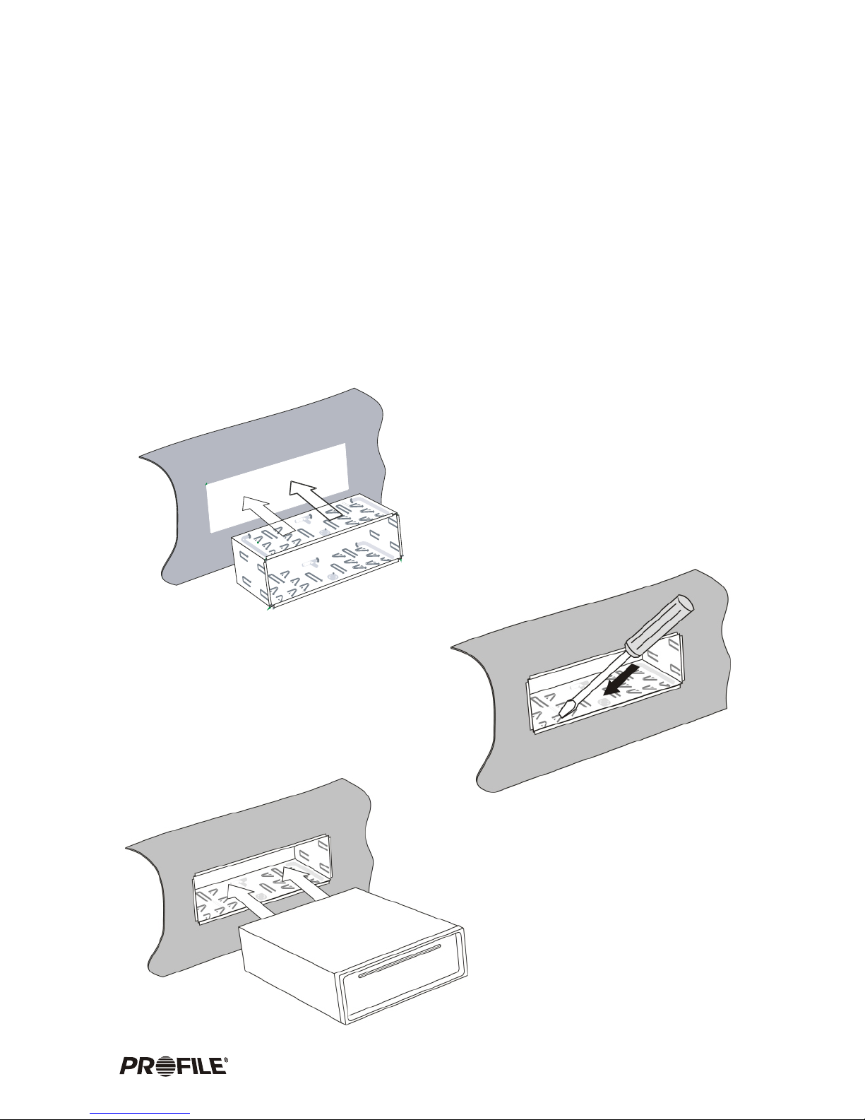
DIN SLEEVE MOUNTING
Insert the mounting sleeve into a
standard DIN cutout in the dash
kit, dashboard or Console.
Bend the mounting tabs of the sleeve
with a screwdriver to secure the bracket
firmly in place.
Insert the CD Player in the
mounting sleeve until it locks.

8MP9900
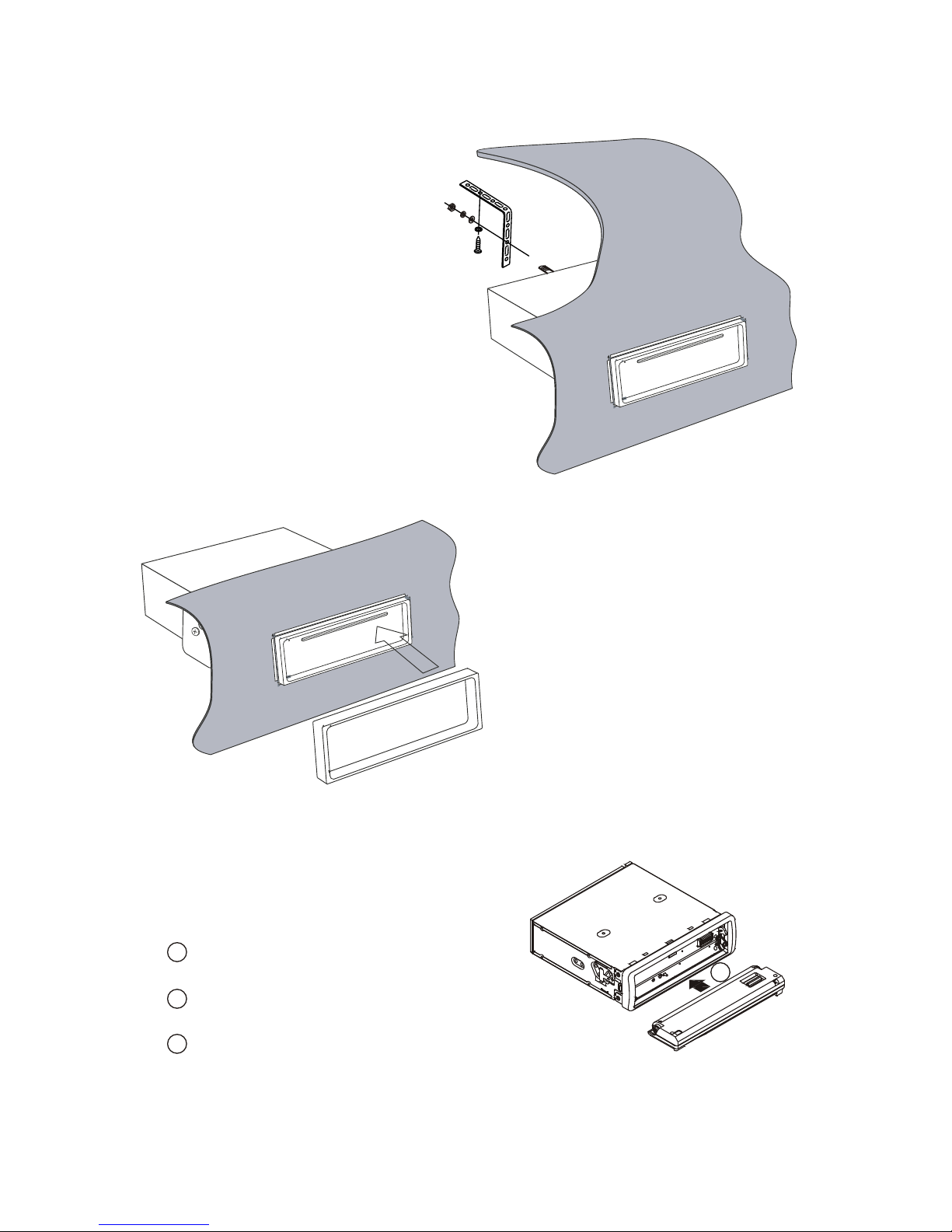
Attach the back brace to the CD
player using the supplied hardware.
Then attach the other end of the
brace to a firm mounting surface
(i.e. Dash brace, fire wall, e.t.c.)
This will brace the back of the CD
player to ensure solid mounting to
prevent theft and provide optimal
CD play.
To Attach the Face Plate:
1 Hold the center of the face plate with the
plate facing down.
2 Insert the plate faced down to the bottom portion
of the unit opening until both left and right side snap in.
3 Then push up the face plate until it clicks into
proper position.
Once the CD player is secured, fit the trim
ring over outside edge of the radio until it
snaps into place.
FACE PLATE
2

9
ISO/DIN MOUNTING
If you own a Japanese vehicle, you can use the standard ISO/DIN mounting screw holes on
the side of the CD player to attach to the existing factory mounting bracket, without using
the provided DIN sleeve.
Remove the factory ISO/DIN mounting bracket from the car along with the factory radio.
Remove the factory radio from the bracket by unscrewing the two Phillips screws on each
side of the radio paying close attention to their screw positions and saving the screws to
mount the CD player.
Remove the sleeve from the CD player by using the keys provided. Also remove the
detachable face and rectangular trim ring from the CD player.
Mount the CD player to the factory ISO/DIN bracket using the screws that you removed
from the factory radio.
Connect the wire harness and antenna cable to the back of the CD player. Then mount the
factory ISO-DIN bracket to the car.
Note: It is not necessary to attach the outer rectangular trim ring for ISO/DIN mounting
method.
REMOVING THE CD PLAYER
To remove the CD player from an ISO/DIN mount, follow the above mounting procedure
in reverse order.
To remove the CD player from a sleeve mount, use the pair of keys provided.
Remove the rectangular trim ring by
applying pressure outward with your
finger tips, then gently pull out away
from the dash.
Insert the provided removal key into an opening slot on each side of the CD player.
Push the keys inward until they unlock the sleeve from the unit. Then pull the CD player
out away from the dash.
PLACE FINGER TIPS HERE
!
!
!
!
!
!
!
Indice
Altri manuali Profile Ricevitore per auto

Profile
Profile CD7200 Manuale di servizio

Profile
Profile CD6500 Manuale di servizio

Profile
Profile CD8200 Manuale di servizio

Profile
Profile MP9700 Manuale di servizio

Profile
Profile CD8700 Manuale di servizio

Profile
Profile PCD970R Manuale di servizio

Profile
Profile PCD950R Manuale di servizio

Profile
Profile CD7400 Manuale di servizio

Profile
Profile PCD920 Manuale di servizio