10 11
1 CAUTIONS
1. To reduce the risk of electric shock, do not open the
machine and maintain by yourself, please consult a
professional service person.
2. To prevent fire or shock hazard, use the power after
safety certification, the input voltage, current, voltage
polarity and operating temperature must meet the
requirements of this camera.
3. Please note the operating temperature and environ-
mental requirements of the camera, avoid too low or
too high temperature. General operating temperature
range of -10°C ~ +50°C (Fahrenheit temperature is
14°F ~ 122°F). Avoid flooding and rain, minimize dust
and moisture erosion, otherwise camera would be
damaged.
4. Cameras in use should avoid direct sunlight, glare,
otherwise the sensor will be damaged.
5. Do not touch the sensor surface, if any foreign
objects exits, a cotton swab or lens paper can be used
to wipe, if it is difficult to remove, a neutral detergent
diluted with water would be useful. Do not use
corrosive solution.
6 Comments & Special Features:
1) The Ultra AHD Series supports True WDR, which
means that the camera will take two exposures with
different settings and then process it into one.
2) While WDR is off, the two exposures will be used for
AHD and Analog (One exposures for each), and the
output (AHD/TVI/CVI/CVBS) is automatically enabled.
3) While WDR is on, the two exposures are used for
HD Output so the Analog output is disabled automati-
cally.
4) While WDR is on the FPS of the camera drops to
30FPS.
5) Any change in the “Special/System” OSD menu
might result with losing the camera’s image and CoC
control. Please do not make any changes without fully
understanding the consequences.
6) In any case of losing picture/CoC control while the
OSD Menu is still open - disconnect the camera from
power and reconnect it to revert the changes.
COLOR SPACE
FRAME RATE
CVBS
VERSION
LANGUAGE
SENSITIVITY
WINDOW TONE
DET V-SIZE
ALARM
ON WEIGHT 0%~100%
ON
MOTION
SHADING
SPECIAL
OFF
OFF
、
SYSTEM
、
、
、
、
BLACK LEVEL
ON
COLOR BAR OFF/ON
LENS ADJ L+L+R+R+C
6. In order to make the camera work smoothly and
obtain asatisfactory image, the power cord and video
connection can not be too long, otherwise the increase
of line loss will lead to the inadequate magnitude of the
operating voltage of the camera or video signal
Inadequate.
7. In order to prevent the camera from falling, please
do not place the camera on an unstable bracket, base
or other unstable objects. Otherwise it will lead to
injury, at the same time, the camera will be damaged.
8. The camera cannot be placed near the radiator or
heating resistor.
2 Product Introduction
2.1 Camera Introduction
PROVISION-ISR’s new series of cameras have
adopted a high performance CMOS image sensor
which provides HD resolution and supports high
resolution video output. The cameras support video
transmission distance of around 400M base on Rg59
standard coaxial cable. This series can support
AHD/TVI/CVI/CVBS 960H analog output.
2.2 Product Features
● Dual Coaxial cable with BNC connenctors
● AHD/TVI/CVI/CVBS Output
● True WDR@30fps(Not Available for Analog Output)
● Motorized 2.8-12mm Vari-Focal Auto Focus Lens
● Auto Day/Night (ICR)
● Defog, HBLC, BLC
● 2D/3D Noise Reduction
● Motion Detection, Privacy Mask
3 OSD Controller
3.1 OSD Control:
Center: Enter OSD/ Enter
Up: Navigate OSD up
Down: Navigate OSD Down
Left: adjust OSD Menu values
Right: adjust OSD Menu values
3.2 Lens Cotrol:
Zoom-In: Press UP continuously
Zoom-Out: Press Down continuously
Focus-: Press Left continuously
Focus+: Press Right continuously
3.3 Output adjustment:
AHD: press center for 3 Second and then Right
TVI: press center for 3 Second and then Left
CVI: press center for 3 Second and then Up
4 Control Over Coaxial(CoC)
4.1 AHD/TVI:
Click on “Iris+” button from the DVR’s PTZ interface to
call the OSD Menu. Use the PTZ interface to scroll
through the menu and “Iris+” to confirm.
4.2 CVI:
Click “
►” button from the DVR’s PTZ interface, then
click “ ” and press “Enter” to call the OSD Menu.
5 Product Installation
5.1 General Notes
1. Make sure the unit is powered off before installation.
2. Check power supply voltage consistent with the
electric voltage to prevent voltage unworthy, resulting
in damage to the device.
3. Do not use in the environment beyond the boundar-
ies of the temperature, and maintain good ventilation
to prevent the rain in order to reduce the risk of fire or
electric shock.
4. The installation and maintenance of this product
should be professional, please do not in any way to
remove or modify the equipment; can only use the
required accessories of manufacturers. Problems
caused by unauthorized repair are at your own risk.
5.2 Installation Tools and Information
Prepare the required engineering data and instruc-
tions. Before installation please prepare the following
tools and instrumentation: A straight or a
Phillips-head screwdriver, multi-meter, scissors,
needle nose pliers, tape measure, pencil and so on.
5.3 Installation Method
1. Check the equipment whether it is damaged.
2. Mounting bracket or base.
① If the cement wall, install the expansion screws
(expansion screw holes need stand or base hole), and
then mount bracket or base.
② If the wooden wall, use self-tapping screws to
mount.
3. Mounting the camera
a. Dome Camera
Adjust the lens position and make it aim at the
monitoring points and present a clear picture, manual-
ly fix lens location and adjust the hemisphere cover.
Re-examine the screen whether the character meets
the requirement. Tighten the hemisphere cover.
b. Bullet Camera
Adjust the body so that the lens aims at the monitoring
points and presents a clear picture. Tighten the
screws, to ensure that it does not move.
Note:
The wall needs to bear at least
3X weight of bracket (base) and
camera.
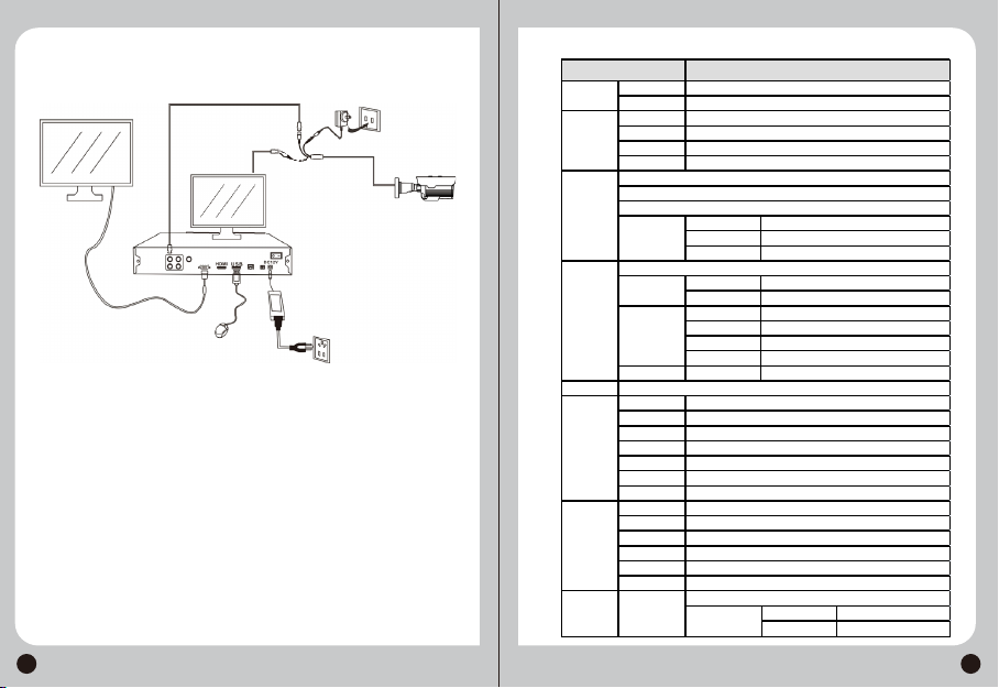
5.4 Connections
Connection as shown in the figure below:
5.5 Lens Control
Use the DVR PTZ interface Zoom+/- to control the
motorized lens.
5.6 OSD Control
The preffered control method is CoC (Control over
Coax). If your AHD DVR supports this function*, Use
the DVR’s PTZ interface to call Preset 95 or press on
“Iris+” to open the OSD menu. Navigate through the
OSD menu by the PTZ direction arrows. “Iris+”
performs as “Enter”.
*All of Provision-ISR’s DVRs support CoC Starting from version 3.4.4
RESET ON
EXIT
OFF
ZONE NUM
H-POS
ZONE DISP
V-POS
H-SIZE
V-SIZE
Y LEVEL
CR LEVEL
CB LEVEL
0~15
OFF/ON
0~60
0~34
0~60
0~34
0~20
0~20
TRANS 0~3
0~20
PRIVACY