7
Bladder Pump Operation in Low-Submergence
QED sampling bladder pumps fill by hydrostatic pressure. As the inside of the pump's bladder
fills with water, the bladder expands. This filling and expanding of the bladder is referred to as
the "refill" half of the pump cycle. When air pressure is applied to the outside of the bladder, the
bladder is squeezed, forcing the water up the discharge tubing. This is referred to as the
"discharge" half of the pump cycle. In low-submergence applications, there is less water pres-
sure available to expand the bladder during the refill.
This can result in a smaller volume of water being pumped with each pump cycle because the
bladder may not fully expand.
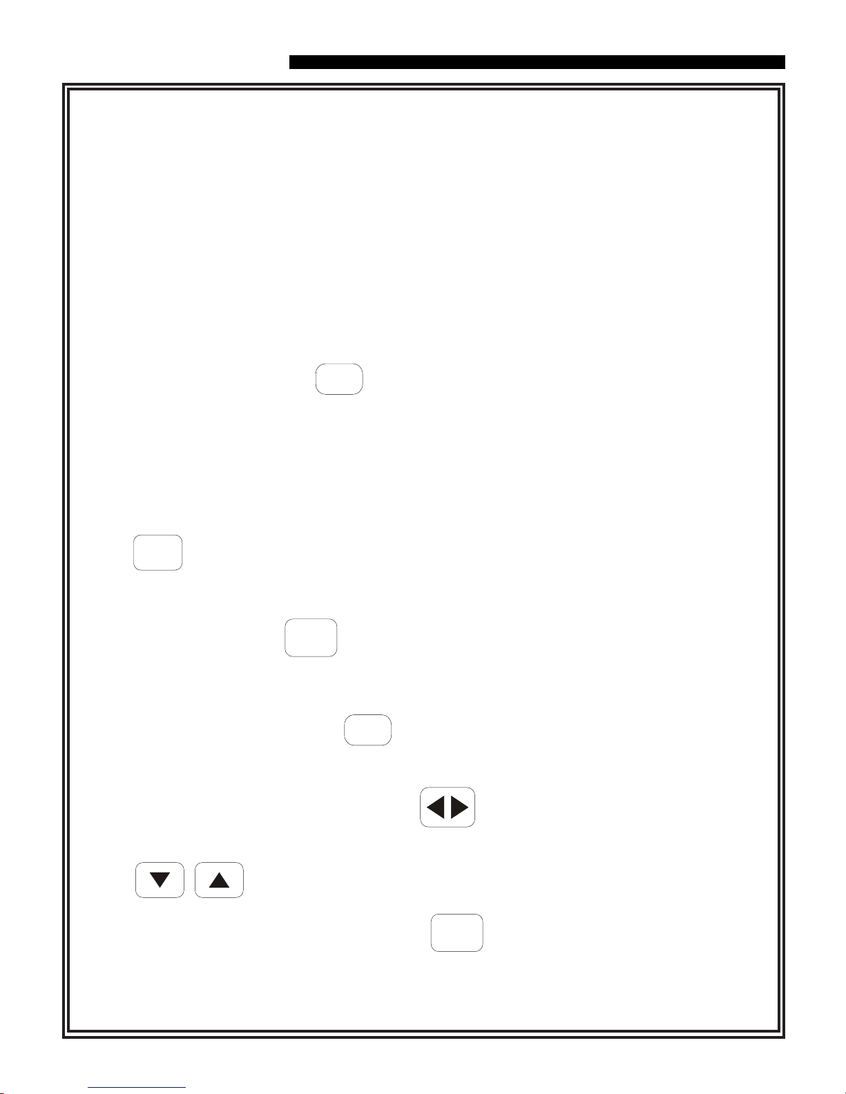
As a result of the lower volume per cycle, more time will be required to bring the water to the
surface. An easy way to verify that the pump is working, prior to the water reaching the surface,
is to submerge the pump's discharge tubing in a beaker of water. Each time the pump goes into
discharge, air in the discharge tubing, which is displaced as the water level in the tubing rises,
can be seen as air bubbles coming from the end of the tubing. To optimize the pumping rate,
the refill time should be set long enough to achieve the maximum volume of air bubbles on
each pump cycle, and the discharge time should be set long enough to ensure that the air has
stopped bubbling out of the tube before the pump controller switches back into refill.
In low submergence wells, it is critical that the air pressure driving the pump not be more
than 10-15psi higher than the minimum re-quirement of 0.5 psi per foot of pump depth.
Higher pressures than this can cause the bladder to be squeezed too tightly during discharge,
a condition which can prevent the bladder from expanding during refill. To avoid this condition
in deeper wells, it is suggested that the air pressure applied to the pump be gradually increased
as the water level in the pump's discharge tubing rises. It is recommended that the air pressure
be set at 15 psi initially, and slowly increased in increments of 10 psi as needed until the water
reaches the surface. Submerging the end of the discharge tubing under water as described
above will verify whether the air pressure is set high enough.
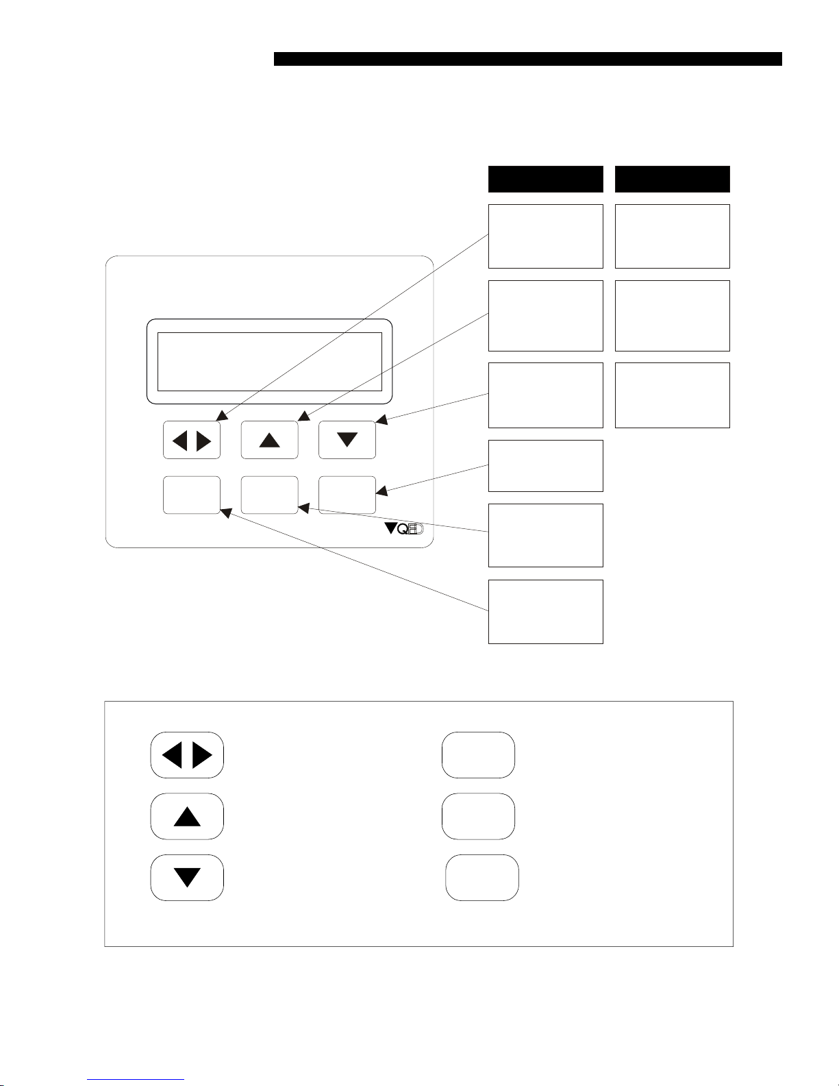
Bladder Pump Operation in Low-Submergence Applications
Pump submergence is defined as the height of the static water column above the top of the
pump. In wells in which this water column height is 5 feet or less, the pump is considered to be
in a low-submergence application.