QUALISYS Q ACADEMY AMTI GEN 5 Documento tecnico

QUALISYS AB
Kvarnbergsgatan 2 · 411 05 Gothenburg · SWEDEN
Tel. +46 31 336 94 00 · Fax +46 31 336 94 20
sales@qualisys.com · www.qualisys.com

1
INTRODUCTION
The AMTI Gen 5 system allows you to connect and
control AMTI force plates. The system works through a
digital amplifier that collects the force plate data and
transmits them to QTM in sync with the data being
collected by the Qualisys camera system.
This tutorial covers how to connect and begin using your
AMTI Gen 5 system with your Qualisys camera system.
For advanced settings beyond the scope of this tutorial,
please refer to your QTM manual or to your AMTI documentation.
CONTENTS
DOWNLOADING THE GEN 5 DRIVER............................................................................................................................2!
CONNECTING THE GEN 5 ........................................................................................................................................................4!
Computer to Gen 5.......................................................................................................................................................................4!
Camera system to Gen 5........................................................................................................................................................4!
SETTING UP THE GEN 5 IN QTM......................................................................................................................................5!
Installing the driver.......................................................................................................................................................................5!
Setting up in QTM.........................................................................................................................................................................6!
Setting the calibration parameters............................................................................................................................... 7!
L-FRAME PLACEMENT................................................................................................................................................................9!
LOCATING THE FORCE PLATE IN THE VOLUME .......................................................................................10!
Recording the force plate’s location ........................................................................................................................ 10!
Identifying the location in QTM......................................................................................................................................11!
Testing and changing the force plate’s orientation...................................................................................13!
SETTING A THRESHOLD.........................................................................................................................................................15!
DOWNLOADING THE GEN 5 DRIVER
2
DOWNLOADING THE GEN 5 DRIVER
The amplifier runs on the AMTI Gen 5 driver, which you will need to download before
connecting the amplifier. You only need to go through this process the first time you
use the Gen 5 system with this computer.
1. Open QTM and select your current project.
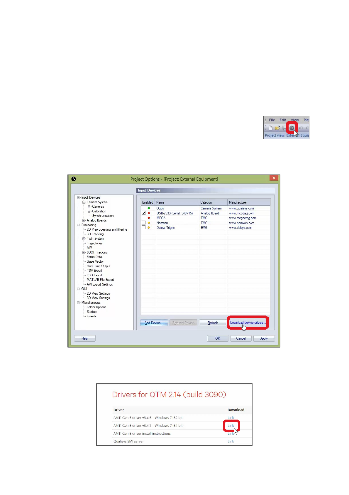
2. In QTM, open Project Options either by clicking the gear icon
near the top left of your screen or by typing the keyboard
shortcut Ctrl+W.
3. With the Input Devices window open, click “Download device drivers” near the
bottom right. The link will open a Qualisys webpage with updated device
drivers.
4. Click on the correct download link for “AMTI Gen 5 driver,” depending on
whether your computer runs 32-bit or 64-bit Windows, then click on the
downloaded file to view it on your computer.

DOWNLOADING THE GEN 5 DRIVER
3
5. The drivers will be in a compressed folder, so you will need to extract the
contents.
6. Follow the extraction instructions, choosing a location on your computer that
you will remember later on during installation.
CONNECTING THE GEN 5
4
CONNECTING THE GEN 5
In order to record and sync the force plate data through QTM, you’ll need to connect
your Gen 5 amplifier both to the computer and to the Qualisys camera system. You
will also need to make sure your force plate is connected to the amplifier according
to your AMTI documentation.
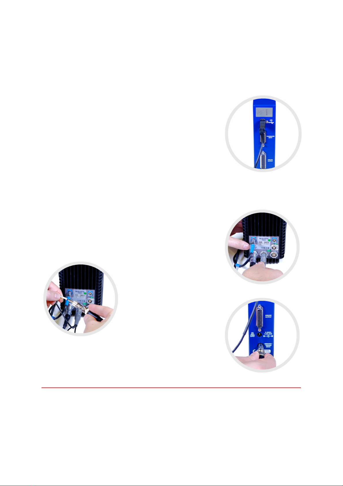
Computer to Gen 5
Your Qualisys computer connects to the Gen 5 system
through a USB Type A to Type B cable. Plug the squarish
end into the USB port on the back of the Gen 5 amplifier,
and plug the flat rectangular end into your computer.
Camera system to Gen 5
To synchronize the force plate data with your Qualisys camera system, you will need
to use the Sync/Trig splitter—a short cable with a single connector branching off into
two or three connectors (depending on the model)—and a long BNC cable.
1. Plug the single end of the Sync/Trig splitter into
the port labeled “CONTROL” on the back of the
nearest Qualisys camera, making sure to line up
the red dots before pushing in.
2. Connect the BNC cable to
the “Sync out” end of the
Sync/Trig splitter, twisting to
secure it.
3. Plug the other end of the
BNC cable into the
“GENLOCK/TRIGGER INPUT”
port on the back of the Gen 5.
The camera is now connected
to the amplifier.
SETTING UP THE GEN 5 IN QTM
5
SETTING UP THE GEN 5 IN QTM
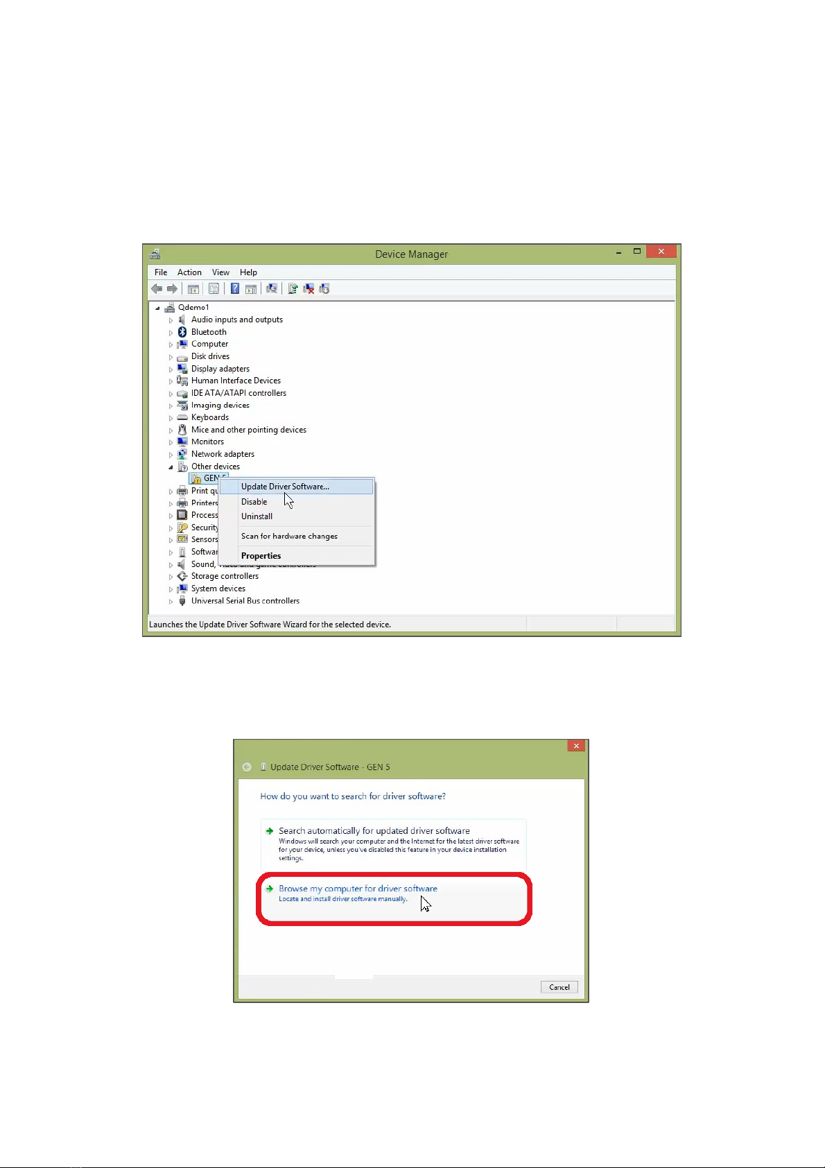
Your computer should automatically prompt you to install the device driver when you
plug in the amplifier. If it doesn’t, open Device Manager, right-click on Gen 5, and click
on “Update Driver Software.”
Installing the driver
1. With the “Update Driver Software” window open on your computer, click on
“Browse my computer for driver software.”
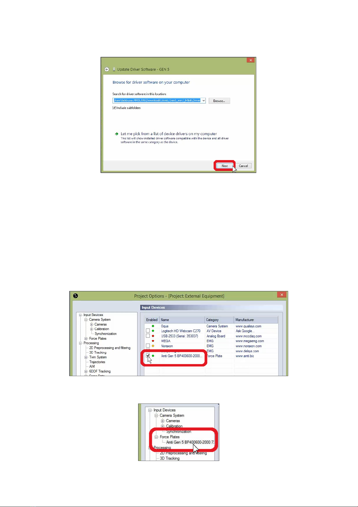
2. Click “Browse,” then choose the folder to which you extracted the driver
earlier.
SETTING UP THE GEN 5 IN QTM
6
3. Click “Next,” and Windows will install the driver.
4. When the installation finishes, click “Close.”
5. You will need to close QTM as well before continuing.
Setting up in QTM
Once the Gen 5 driver has been installed, reopen QTM and select your current
project so you can adjust the amplifier’s settings.
1. Open Project Options as before by clicking the gear icon near the top left of
your screen or by typing the keyboard shortcut Ctrl+W.
2. In the Input Devices window, you will see a green circle next to the AMTI Gen
5 indicating that the amplifier is plugged in. Select the checkbox next to it, and
“Force Plates” will now show up under Input Devices in the list to the left.
3. Click the plus sign beside “Force Plates,” then click on “Amti Gen 5” to change
its settings.
SETTING UP THE GEN 5 IN QTM
7
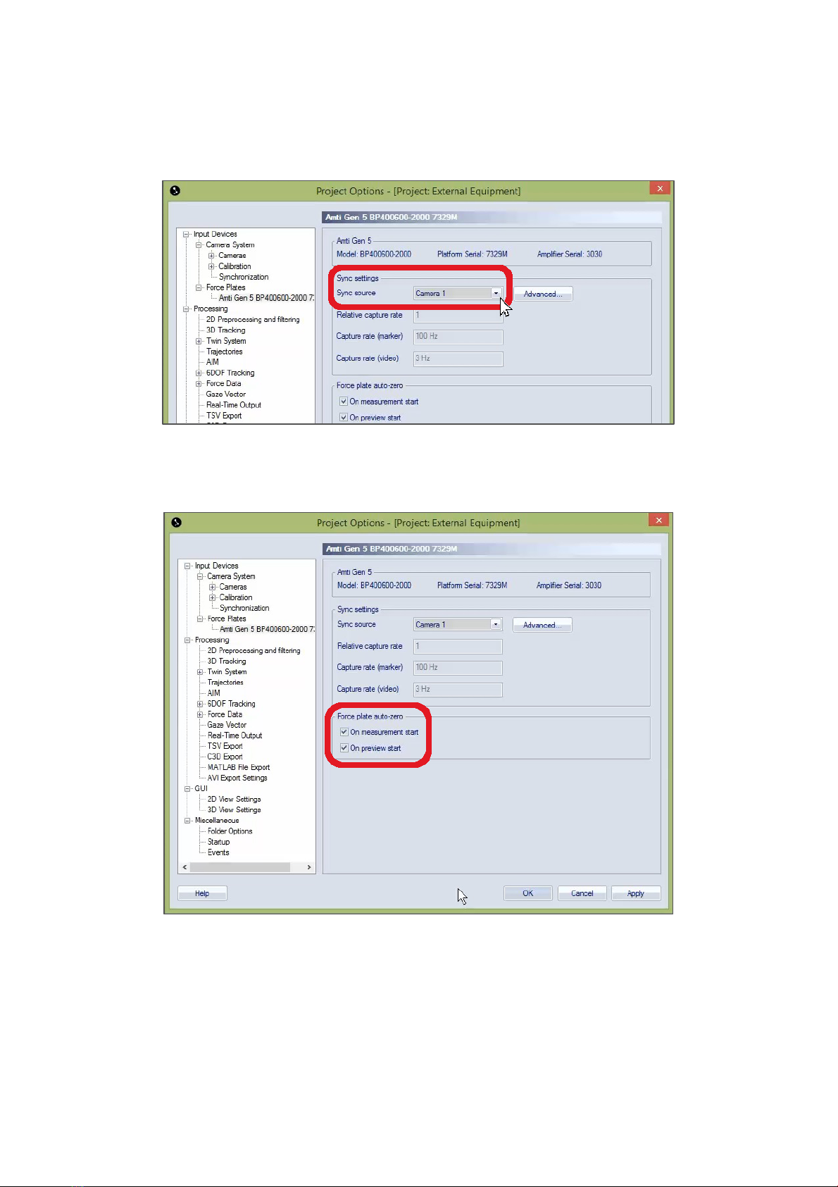
4. In the settings window, specify the camera number to which your amplifier is
connected by using the dropdown menu beside “Sync source.” (The number is
displayed in the bottom right-hand corner on the front of the camera.)
5. It is recommended to zero your force plate(s) before each trial, and you can
automate this by selecting one or both of the checkboxes under “Force plate
auto-zero.”
6. Click “OK” to save your settings.
Setting the calibration parameters
If you are using a digital force plate, QTM will receive the calibration matrix
automatically from the amplifier. However, if you are using an analog force plate, you
can set the calibration parameters manually.
SETTING UP THE GEN 5 IN QTM
8
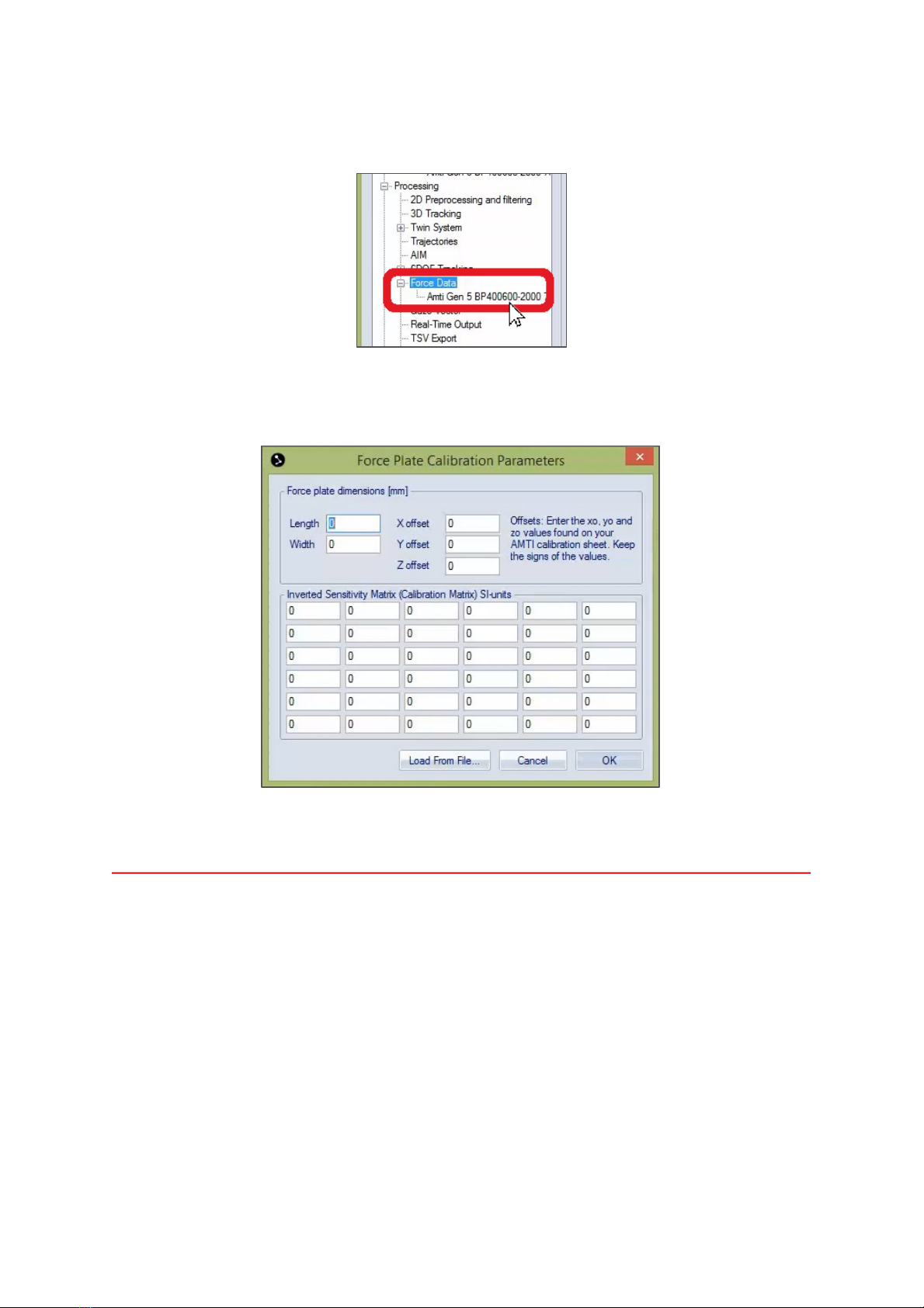
1. In the left pane of the Project Options window under “Processing,” click on the
plus sign next “Force Data” and then on “Amti Gen 5.”
2. Next, click on “Calibration” to input the force plate calibration parameters
(length, width, offsets, calibration matrix, etc.) according to your AMTI
documentation.
3. Click “OK” to save your calibration parameters and close the window.

L-FRAME PLACEMENT
9
L-FRAME PLACEMENT
Before starting data acquisition, you will need to calibrate the cameras so that the
computer will know exactly where the cameras are in respect to each other and to
the environment around them. This tutorial does not cover how to calibrate the
camera system, but it is important to note that the location of the force plate often
determines the origin point for calibration.
The L-frame is a tool that defines the X, Y, and Z axes of
the volume during calibration, and its corner sets the
origin point. Many labs choose to place the L-frame along
a force plate. Tabs on the L-frame are designed to slide
into the gaps beside the force plate to keep the L-frame
in place.
The L-frame does not have to
be placed on the force plate.
The important thing is that it be placed in the same spot
every time for consistent calibration results, and the force
plate is an easy reference point.
Indice


