Raybar LINCE 150 Manuale utente

RY-150LC
USER manual

PREFACE
Thank you for Choosing Raybar LINCE 150/RY-150LC motorcycle. We wish you a happy and reliable riding.
We are committed to customer satisfaction. We strive to provide great user experience by product innovation and excellent after
sales support.
This user manual is guide for you to understand function of various parts, riding operation, maintenance schedule and basic
maintenance of your new Raybar motorcycle. Please go through this manual to understand your motorcycle before using it.
Please contact your dealer for detailed information about the product and for after sale services.

CONTENTS
Motorcycle identification............................................................................................................................................................... 01
View and part names
Front top view...................................................................................................................................................................... 02
Right side view......................................................................................................................................................................03
Left side view........................................................................................................................................................................04
Parts function..................................................................................................................................................................................05
Inspection before riding.................................................................................................................................................................. 10
Starting engine & riding operation...................................................................................................................................................11
Maintenance schedule....................................................................................................................................................................12
General inspection & repair............................................................................................................................................................. 13
Technical specification.................................................................................................................................................................... 15
Electrical circuit diagram................................................................................................................................................................. 17

(1)
Note - Frame number and engine number is usually required for vehicle registration and insurance purpose.
Engine serial number is engraved on
crankcase assembly.
Vehicle identification number (VIN) is
stamped near main stand.
Frame number is engraved on main
tube of frame.
Engine Number VIN number Frame number
MOTORCYCLE IDENTIFICATION
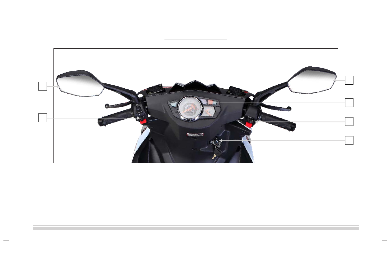
FRONT TOP VIEW
(2)
1. Rear view Mirror
2. Left handle bar switches
3.
4. Right handle bar switches
5. Ignition switch
Speedometer
1
1
5
4
3
2
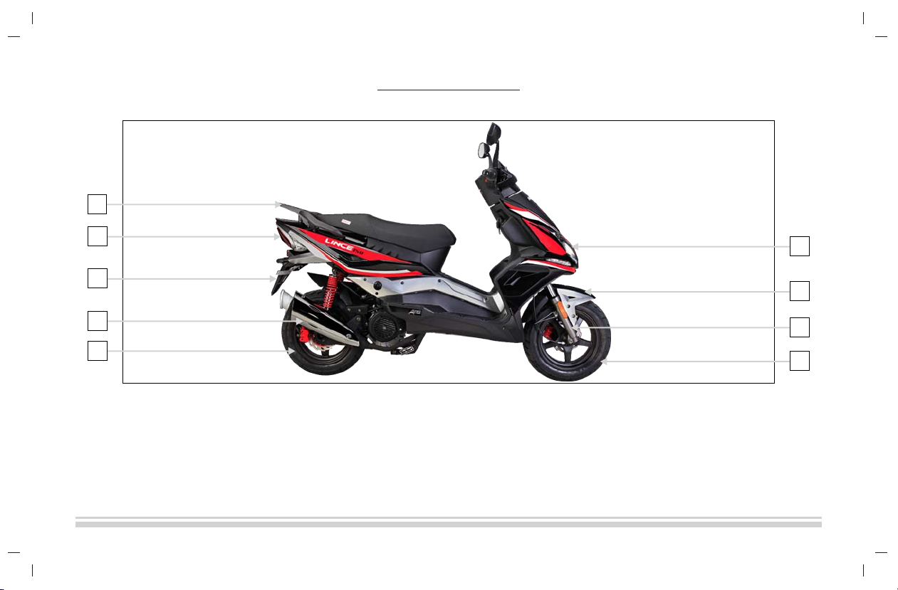
(3)
1. Rear grip
2. Tail lamp
3. Rear fender
4. Muffler
5. Rear tyre
6. Head lamp
7. Front fender
8. Front suspension
9. Front tyre
1
3
26
7
8
9
5
4
RIGHT SIDE VIEW

(4)
1. Indicator
2. Front disc brake
3. Front wheel
4. Seat
5. Rear wheel
6. Side stand
7. Main stand
4
5
6
7
1
2
3
LEFT SIDE VIEW

Meters and indicators
1. Odometer – Records accumulated riding distance.
2. Speedometer – Displays riding speed of motorcycle.
3. “ ” High beam indicator – Indicator turns ON when head lamp is in high beam.
4. Turn signal indicator left – Flashes when left turn signal switch is operated.
5. Turn signal indicator right – Flashes when right turn signal switch is operated.
6. Fuel Gauge – It indicates level of fuel contained in fuel tank.
7. Ignition switch –
(a) OFF position – All electrical circuits are cut off. The engine cannot be started. The key
can be removed in this position.
(b) ON position – The ignition circuit is completed. Engine can now be started. The key
cannot be removed in this position.
(c) LOCK position – To lock the steering, turn the handlebar all the way to the left. Push down the key and rotate to “LOCK”
position, let the key come up and now remove the key.
(5)
1
2
5
4
6
7
3
PARTS FUNCTION

Left handlebar control switches
1. Headlamp dimmer switch- This switch is used to change headlamp position from low
beam to high beam or vice versa.
2. Horn switch – Press the switch to operate the horn.
3. Turn signal switch – Operate the switch when turning right or left by pushing the switch
towards right or left.
(a) Turn right position – The right turning lamp and right turn signal Indicator on
instrument panel flashes.
(b) Turn left position–The left turning lamp & left turn signal indicator on instrument
panel flashes.
3
1
2
(6)

Right handlebar control switches
1. Headlamp switch –
(a) “ “ position – The headlamp , front parking light and tail lamp are turned ON.
(b) “ “ position – All lamps are turned OFF.
(c) “ “ position – Front parking lamp and tail lamp are turned ON.
2. Electric starter switch – When this switch is pressed, starter motor cranks the engine. This
switch should not be pressed over 5 seconds continuously.
Seat
To open the seat insert the ignition key into seat lock and rotate. Then hold the seat and lift it up.
To lock the seat put it down and press downwards.
Fuel tank & Fuel tank cap
The capacity of the fuel tank is 5.5L.
(a) Position of the fuel tank – Fuel tank is mounted beneath the seat.
(b) Opening fuel tank cap –First you need to open the seat, then rotate the fuel tank cap
in anti-clockwise direction.
(c) Closing fuel tank cap - To close fuel tank cap, place the cap on fuel filling neck of fuel
tank and rotate it in clockwise direction.
1
2
(7)
Questo manuale è adatto per i seguenti modelli
1
Indice
Altri manuali Raybar Motociclo


 Manuale")


