RCT Power DC 8.0 Manuale utente

SETUP
Installation
Power Storage DC 8.0 / 10.0
This setup manual contains a short instruction required for
installing, wiring, commissioning and operating the inverters.
For further instructions on installing or operating, please refer
to the detailed user manual, which you can access via
www.rct-power.com.
RCT Power GmbH reserves the right to make changes to
specifications or documents without prior notice.
RCT Power GmbH shall not be responsible for any damages
resulting from use of this document.
This document does not replace any applicable laws,
regulations, standards or codes.
Warranty conditions come enclosed with the device. No
warranties can be derived from this document.
Intended Product Usage
To prevent personal injury or property damage,
the inverter must only be installed, wired,
connected, commissioned, maintained and
serviced by qualified personnel:
•
Trained in installing electrical devices.
•
Familiar with all applicable laws, regulations, standards and
codes for electrical devices.
•
Familiar with safety requirements and safety-related
guidelines for electrical devices.
•
Familiar with work protection laws and regulations.
•
Using the appropriate personal protective equipment.
Power Storage DC 8.0 and 10.0 are stationary 3-phase string
inverters with integrated battery charger. They convert direct
current (DC) supplied by the PV array and the battery into
alternating current (AC), which can be fed into the electricity
grid.
They are not designed for any other application or connection
to other devices.
Any use that differs from or goes beyond the intended usage is
considered misuse. RCT Power GmbH shall not be liable for any
damage resulting from misuse.
Any misuse will terminate warranty, guarantee and general
liability of the manufacturer.
In 7 Steps to the installed system
EN
Symbols
Level of risk
Explanation
high
medium
low
Immediate danger
of death or serious
injury
Immediate danger
of minor or
moderate injury
Danger of
equipment or
property damage

2
Assembly and mounting.
(Section 2, p.3).
Electrical connection of the devices.
(PV, grid, battery section 3, p.4-5 /
Communication section 4&5, p.7-8 and section 7, p-11 /
Power Switch, Power Sensor section 6, p.9-10).
Switch on Inverter (switch on fuses).
(Section 8.1, p.12).
Access to the inverter via APP.
(Steps 1 to 7 under section 8.2, p.13).
Configure the Power Switch, if available.
(See Manual, Power Switch).
Configure the inverter, select the land and norm.
(Steps 8 to 11 in the setup section 8.3, p14).
Configure the battery and Power Sensor classification.
(Steps 12 to 16 in the setup section 8.3, p.14-15).
The configuration of the battery is now complete.
After the inverter has checked the specifications, it starts charging the battery.

3
[1] Scope of Delivery
Fig.1
Look over
user manual.
Wait 10 minutes after
disconnection before
touching inner parts.
Hot surface
Electrical device:
grounding necessary
[2] Inverter Mounting
Item
Description
A
Setup manual
B
PV input- and battery connectors (Weidmüller
PV-Stick)
C
Wall bracket
D
Inverter
a
LCD display for information on inverter operation
b
DC switch
c
DC PV plugs
d
Cable entries for communication ports
e
Cable entry for AC cable
f
Screw hole for additional protective grounding
g
Name plate with technical data, serial number, symbols
h
DC battery plugs
i
RJ45 connectors:
Battery, Power Sensors and Power Switch
Item
Description
A
Select non-flammable, firm wall. Room may not contain
highly flammable goods, liquids or gas.
B
Protect from snow, rain, direct sunlight and dust.
Observe allowed ambient temperature (-25 … 50°C).
Maximum degree of pollution PD2.
C
Mount in upright position. Ensure enough space for easy
access. Make sure wall supports inverter weight.
D
Minimum clearance: half of inverter width at both sides
and half of height at top and bottom.
E
Do not place inverter in closed cabinet.
Step
Description
1
Attach wall bracket firmly to wall with 3 to 6
screws (ø 6 to 8 mm), matching wall plugs and
washers (outer ø min. 18 mm). Material not
included in delivery.
2
Take out locking screw of inverter at the top
left and right sides.
Hook inverter onto wall bracket and fix
locking screw back.

4
[3] Electrical Connection
[3.1] Overview Connection Parts
Fig. 2
The electrical connection for a second parallel battery is provided.
The function for a second parallel battery is currently not integrated.
A parallel battery cannot be operated at present.
[3.2] AC Connection
Risk of death or injury due to electric shock!
While the inverter is connected to grid (AC voltage
source), to PV array which is exposed to sunlight (DC
voltage source) or to the battery (DC voltage source),
high voltage is present in cables and inner parts of
inverter.
•
Important: All voltage sources (DC / PV-generator, DC /
battery and AC / utility grid) must be disabled before any
electrical work.
To disable PV-generator DC voltage connection turn DC
switch to 0-position and wait 10 minutes before continuing.
To disable AC voltage connection turn off AC switch, main
breaker or fuse. Make sure, other persons don’t switch back.
Do not enable voltage connections until work is finished.
•
To disable DC battery voltage connection both voltage
sources (DC / PV-generator and AC / utility grid) must be
disabled.
•
During AC connection: Do not exchange L, N and PE wires!
•
Make sure other persons keep away during electrical work.
Risk of death or injury due to electric arc!
Disconnecting DC plugs under load can cause
electric arcs.
Risk of damage due to improper installation
and operation or misuse.
•
Contact local utility company or grid operator before
connecting inverter to grid.
•
Provide for an AC disconnection device
(typical miniature circuit breaker 3 pole 6kA, B-
characteristic 25A).
•
If required in country or installation, install a
residual-current device (RCD), or residual-current
circuit breaker (RCCB).
•
Inverter contains no owner serviceable parts.
Contact local authorized personnel for service.
•
Do not remove name plate.
•
Only RCT Power certified batteries complying with
the demands of the certain region are allowed to be
used.
Item
Description
A
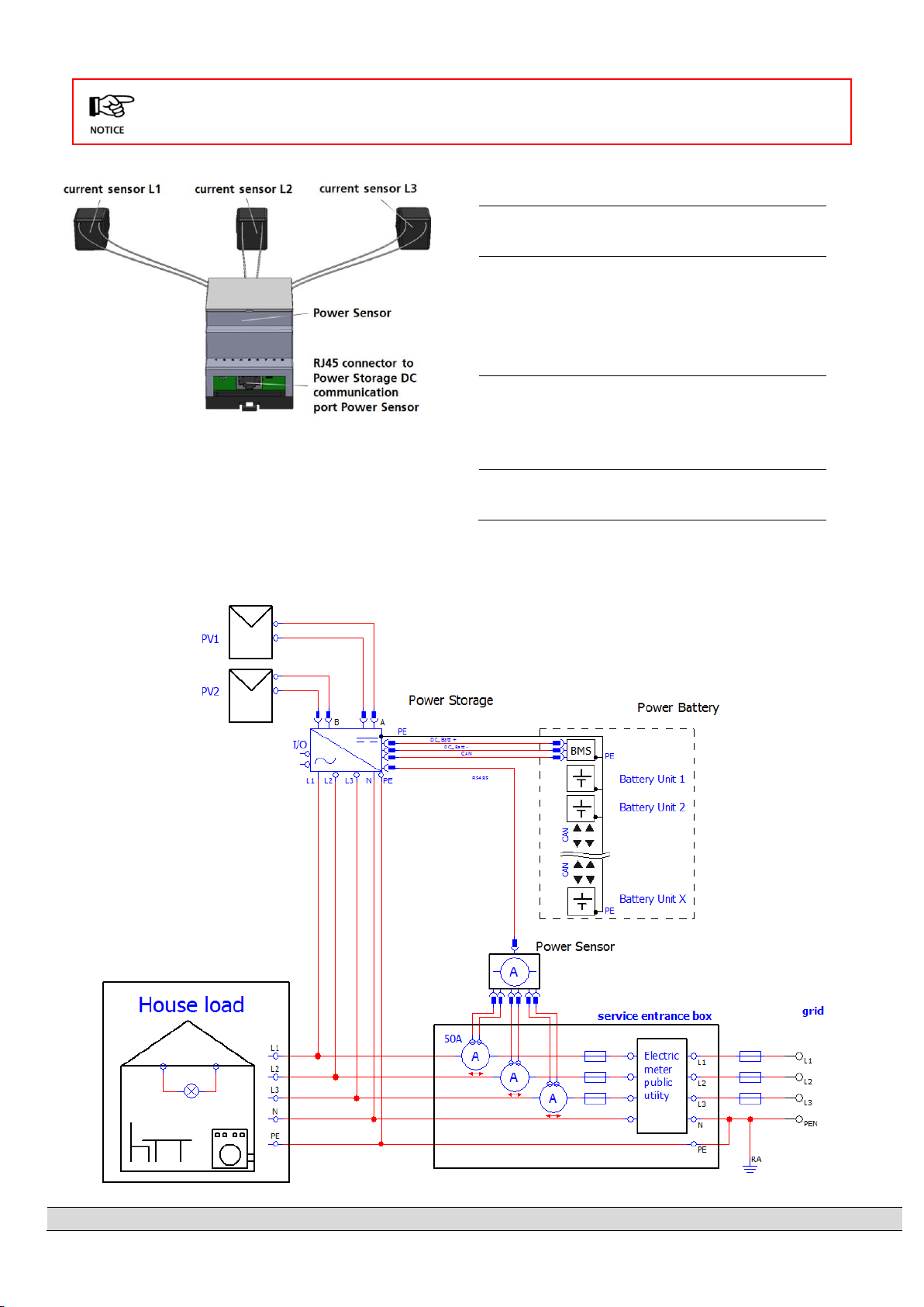
AC terminal block for L1, L2, L3, N and PE phases.
B
Clamps for parallel DC mode.
C
Communication board.
D
RJ45 Connectors for
Battery, Power Sensor and Power Switch.
E
RJ45 socket for
connection of the Ethernet interface.

5
[3.3] DC Connection
[3.4] DC Parallel Mode
Material not included in delivery.
This section applies only, if several Strings with an equal
amount of modules are to be connected in parallel and the
maximum input current per input therefore exceeds 14A.
Step
Description
1
Remove cover of inverter.
2
Connect clamps X101 and X104.
(Show Fig. 2, B).
To prevent personal injury or property
damage, make sure that there is no
PV-DC connector plugged and DC-switch is
“0” in during this installation.
[3.5] DC Battery Connection
Step
Description
1
Remove cover of inverter.
Locate AC terminal block (Fig. 2, A).
2
Feed cable through AC entry (Fig. 1, e). Push
down clamps to insert L1, L2, L3, N and PE.
3
Tighten swivel nut of cable entry.
Step
Description
1
Do not turn plug parts before inserting the cable.
Select correct plugs for polarity of PV and battery
strings.
2
Push cable into plugs straight until the spring
clamp locks.
3
Turn lower part of plug shut.
4
Make sure DC switch is “0”.
Plug corresponding plus and minus poles into
adjacent PV plugs of inverter (Fig. 1, c).

6
Make sure the DC switch of the inverter is set to “0”, the battery ON/OFF switch set to “0” and AC through the main breaker or fuse
is disconnected.
Plug the battery connectors to the inverter.
(The connection cables from the inverter to the battery is not included).
[3.6] Second Protective Inverter Grounding
Material not included in delivery.
If required in the country of installation, attach a second protective earth connection to the housing.
[4] I/O-Board Communication Connection
Fig.3
Communication Ports
[4.1] Connection of Communication Ports
Item
Description
1
X102: serial RS485 interface.
2
X100: Multifunctional Relay, max. 24 V,1A.
3
X101, Power management: 4 digital inputs for
potential free relay contacts.
4
X103: Digital in/out (S0-signals),
max. Input 24 V,
max. output 5 V, 10 mA.
DC cable -
DC cable +

7
[4.2] Wiring of Communication Ports
[5] RJ45 Connectors for Power Battery, Power Sensor and Power Switch communication
The inverter communicates with the batteries via the CAN-Bus.
If the inverter is delivered with an optional Power Sensor or Power Switch please refer to user manual of these items for
further detailed commissioning information.
Fig. 4
RJ45 –Communication Ports
Select correct port (see Fig. 4 ) and insert cables in RJ45 connectors labeled with the suitable port .
[5.1] Wiring of RJ45 –Communication Ports
Description
CAN:
Battery communication connector.
Power Sensor:
Current sensor communication connector.
Power Switch:
Power Switch communication connector.
Step
Description
1
Use the feed cables for the corresponding cable entry (Fig. 1, d).
2
Select correct port (see next section), press down spring clamp, insert cables and release.

8
Standard communication with Power Battery
Additional Power Switch communication
Additional Power Sensor communication
[6] Connection - Power Switch

9
Step
Description
1
Switch off the system (show section 9).
2
Install the Power Switch in the service connection box or
in the near.
3
Connect the Power Sensor and Power Switch via patch cable with the
correspondending RJ45-connectors at the Power Storage DC.
4
For further configurations please refer to user manual.
[6.1] Connection - Power Sensor
This Section applies only in use with a RCT Power Switch and battery system.
Please note for a correct function of the Power Switch is only possible if the entire installation is as TN-
C-S- or TN-S system!

10
Step
Description
1
Place the Power Sensor in the service entrance
box.
2
Click the three current sensors around the
phases L1, L2 and L3 wires in the service
entrance box.
(The order and direction of installation is not
important).
3
Connect the Power Sensor via Patch cable to
the Power Storage DC at the RJ45 connector
X403 “Power Sensor”
(see fig. 4).
4
For further configurations please refer to user
manual.
[7] Connection –Ethernet-Interface
The Power Storage DC system functionality depends on energy consumption measurement. This section
applies only in use with a Power Sensor.
Altri manuali per DC 8.0
1
Questo manuale è adatto per i seguenti modelli
1
Indice
Altri manuali RCT Power Magazzinaggio


