
Red20Rc R630 FPV SPIDER Manuale utente

R630 FPV Spider
Quadcopter

© Red20RC 2014
2
Thank you for purchasing the R630 FPV Spider Quadcopter!
We hope you have a lot of fun building and flying this quadcopter.
REMEMBER
RC Aircraft are not toys! This is a complicated flying machine that
requires skill to build and fly. Whilst the R630 FPV Spider Quad is a
stable and capable flyer, it is not really intended for new pilots.
Make sure you know the rules for the country you are flying in. If in
doubt, seek help from an experienced pilot.
© Red20RC 2014
3
© Red20RC 2014
4
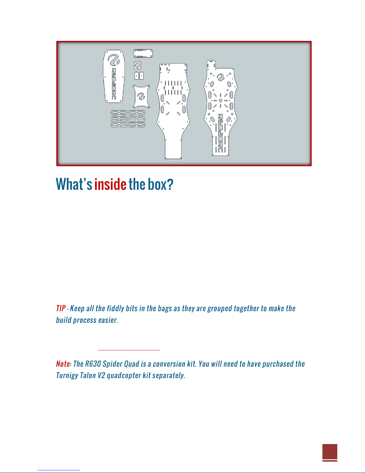
The R630 FPV Spider Quad is supplied in kit form and contains everything you
need to complete the frame:
Top and bottom plates
Acrylic protective hood
Flight controller anti-vibration mount
FPV camera mounting brackets
HD camera vibration isolation plate
ESC mounting fins
A complete fixings and fasteners pack
Although quality is our primary focus, if you find a part is missing or broken
© Red20RC 2014
5
The R630 is not aimed at beginners so it is likely you already have a pretty good
idea of what you are going to use for this build. As a general rule you will need:
Turnigy Talon V2 frame hardware
Motors –28-32 size, 1100kv or lower
ESCs –SimonK flashed 30A
Props –9 to 12 inch recommended
Flight controller –Any suitable controller (we’ve used KK2.1.5 and APM so
far)
Radio receiver
FPV camera (micro 21mm size) and transmitter
Battery –4000 –5200mah 3S LiPo recommended
HD recording camera to capture your exploits!
Motors: NTM 2826 1100kv (short shaft version)
ESCs: MultiStar 30A BEC with SimonK firmware
Flight Controller: KK2.1.5 with Steveis 1.14s Pro firmware
Props: 1055 Carbon Fibre
Battery: 4000 –5200mah 3S LiPo (max thickness 25mm)
Reciever: FRSky V8 HV
Flight Camera: Turnigy IC-120NH Mini CCD Video Camera
Video Transmitter: ImmersionRC 5.8Ghz Audio/Video Transmitter with
ImmersionRC 5.8GHz Circular Polarized SpiroNet Antenna V2
HD Camera: GoPro™ Hero 3 Black edition

© Red20RC 2014
6
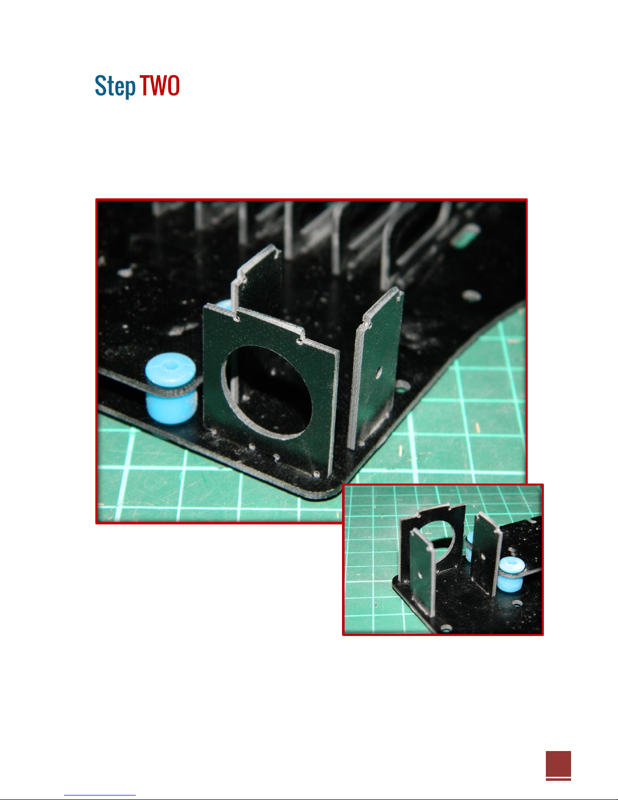
First we need to do the internal structure and some fiddly bits!
Start by mounting the HD camera anti-vibration plate. These vibration balls are a
pain to fit but take your time and you’ll soon get them all in.
Now add the 6 ESC vertical mounting brackets. These will be a tight fit and may
require a little sanding on the edges to get them in. This is intentional as once in
place they require no glue and will be a strong fit.
© Red20RC 2014
7
Finish the internal structure by adding the three plates that make up the FPV
camera bracket.
Again, these will more than likely be a tight fit so take you time and sand a slight
bevel on the edges of the tabs to help with locating them in place if necessary.

© Red20RC 2014
8
The camera mounting bracket is pre-drilled to suit the Turnigy range of micro
FPV cameras.
Access to this area will be difficult later on in the build so now is a good time to
mount the camera using the M2 screws provided with the camera bracket.
© Red20RC 2014
9
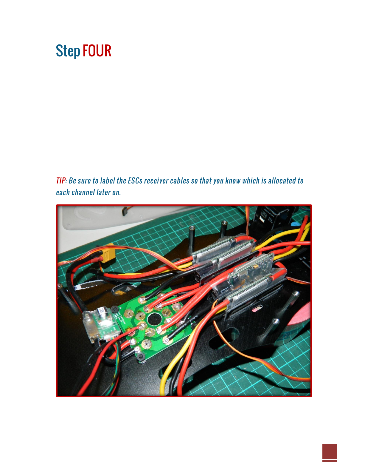
Time to heat up the soldering iron!
The frame is pre-drilled to accept a variety of square pattern power distribution
boards. In the prototype we used the 45mm square 8 output board from
HobbyKing.
Place your ESCs vertically in between the mounting brackets as shown and
solder directly to the PDB. There is a maximum of 25mm depth permissible
inside the frame and most 30A or smaller ESCs should fit within this limit. In the
photo you can see we have placed each set of ESCs “head to toe” and run one
set of cables through the centre channel.
© Red20RC 2014
10
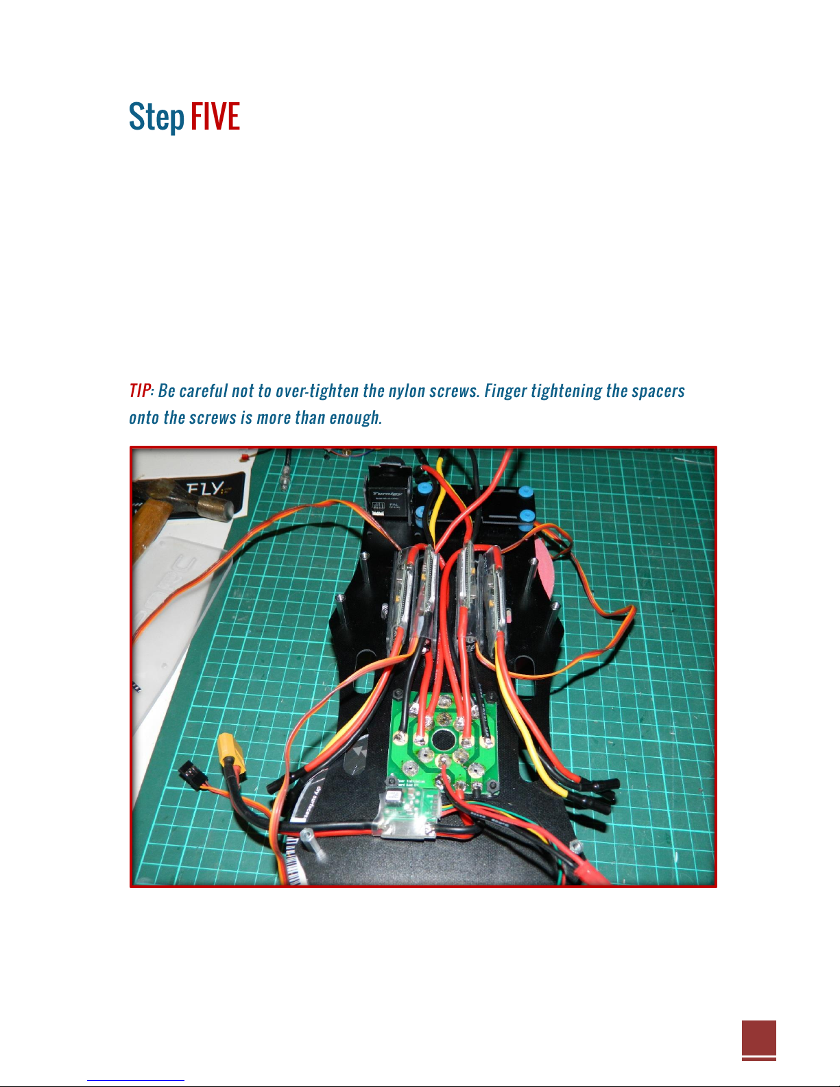
With the internal electronics complete it is now time to start adding the spacers.
Start by adding the 8 20mm metal spaces supplied with the Talon kit. Replace
the countersunk 3mm screws with the M3 x 10mm button head screws
provided.
Next add the remaining 25mm nylon spacers to the bottom plate using the
supplied M3 x 10mm nylon screws. In total there will be 3 black spacers at the
front, 4 at the rear and 2 in the centre. The two in the centre are special and
should have the male ends facing upwards.


