E33 Gas Insert Zero Clearance Kit
Do not install the third screw until
the back panel is installed.
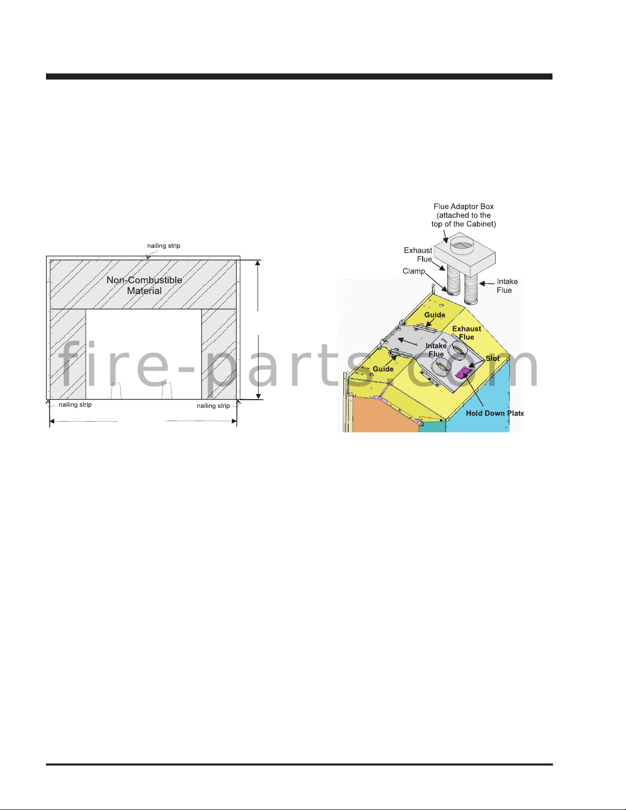
The cabinet face panels have a 1/2" (13mm) lip to defi ne the zones for
combustible and non-combustible facing materials: outside the lip, any
material up to 1/2" (13mm) may be used; inside the lip, only non-combus-
tible materials may be used (with a maximum thickness of 1-1/2" (38mm)).
The kit may be installed directly on and/or against standard combustible
building materials. Refer to Page 3 for diagram.
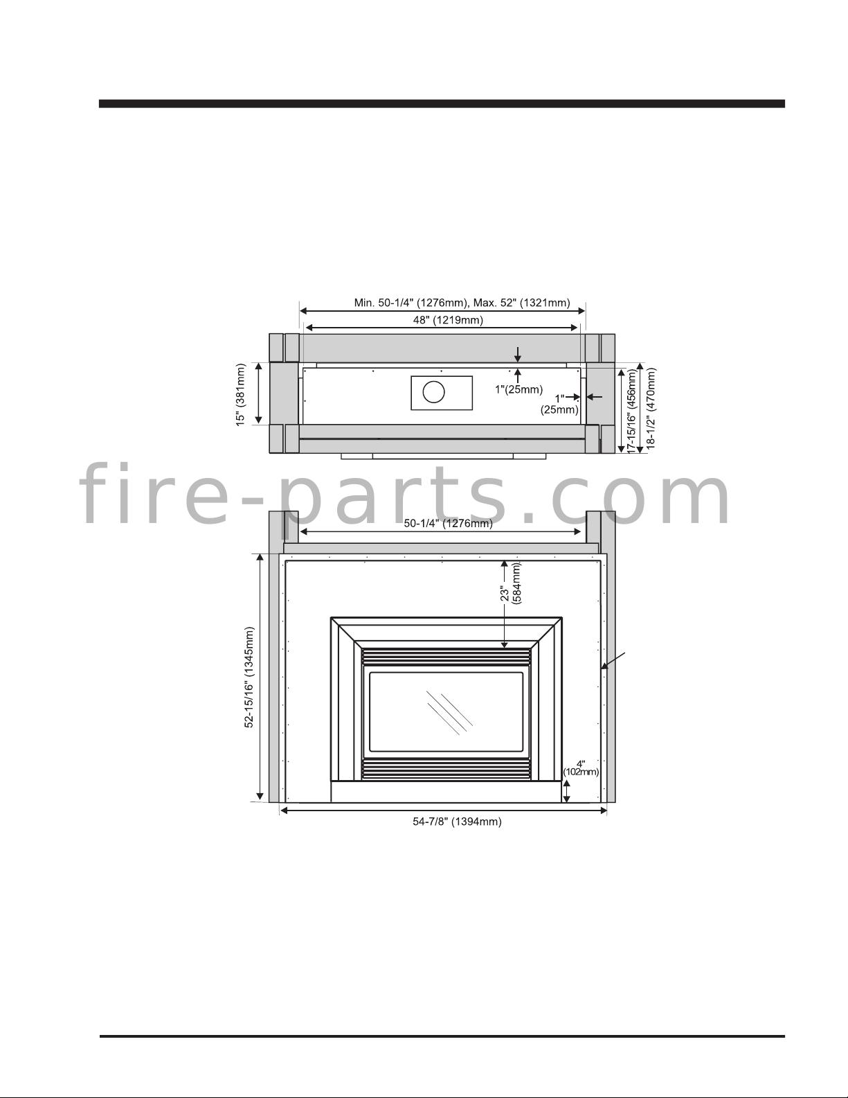
Frame in the enclosure for the Kit with framing material. The framed
opening for the assembled kit is 52" (1321 mm) high x 50-1/4" (1276
mm) wide x 18-1/2" (470 mm) deep. See diagram.
If the interior of the cabinet framing is fi nished (with sheet rock,
for example), The dimensions given are from the inside of the
fi nished surfaces. The ceiling inside the framed enclosure
should be a minimum of 55-1/2" (1410mm) from the base.
For exterior walls, use a vapour barrier and insulate the enclo-
For exterior walls, use a vapour barrier and insulate the enclo-
sure to the same degree as the rest of the house, or according
sure to the same degree as the rest of the house, or according
to local installation codes. In colder climates, if the heater is
to local installation codes. In colder climates, if the heater is
to be installed against an exterior wall or chase, insulate the exterior walls according to local installation codes.
to be installed against an exterior wall or chase, insulate the exterior walls according to local installation codes.
ZERO CLEARANCE KIT ASSEMBLY
ZERO CLEARANCE KIT ASSEMBLY
All pieces join together using the sheet metal screws that are
1) Assemble the Sides and Base sections. The Side sections
fi t inside the lip of the Base section. The wider fl ange on
the Side section is on the front of the kit.
Secure with 2 screws on each side. Leave the 3rd screw
(closest to the rear) until the Back section is attached.
fire-parts.com