4U20/E21 Gas Insert Zero Clearance Kit
PARTS
Included with Kit:
1 Main Body Assembly (5 pieces)
1 Faceplate Top Insulation
1 Zero Clearance Top Louver Assembly
Sold Separately: (Rq)=Required
(Rq) 1 402-918 Faceplate40-1/4"Wx26-1/4"H
(1020mm W x 665mm H)
c/w faceplate trim.
(Rq) 1 532-926 4"(102mm)HearthTrim
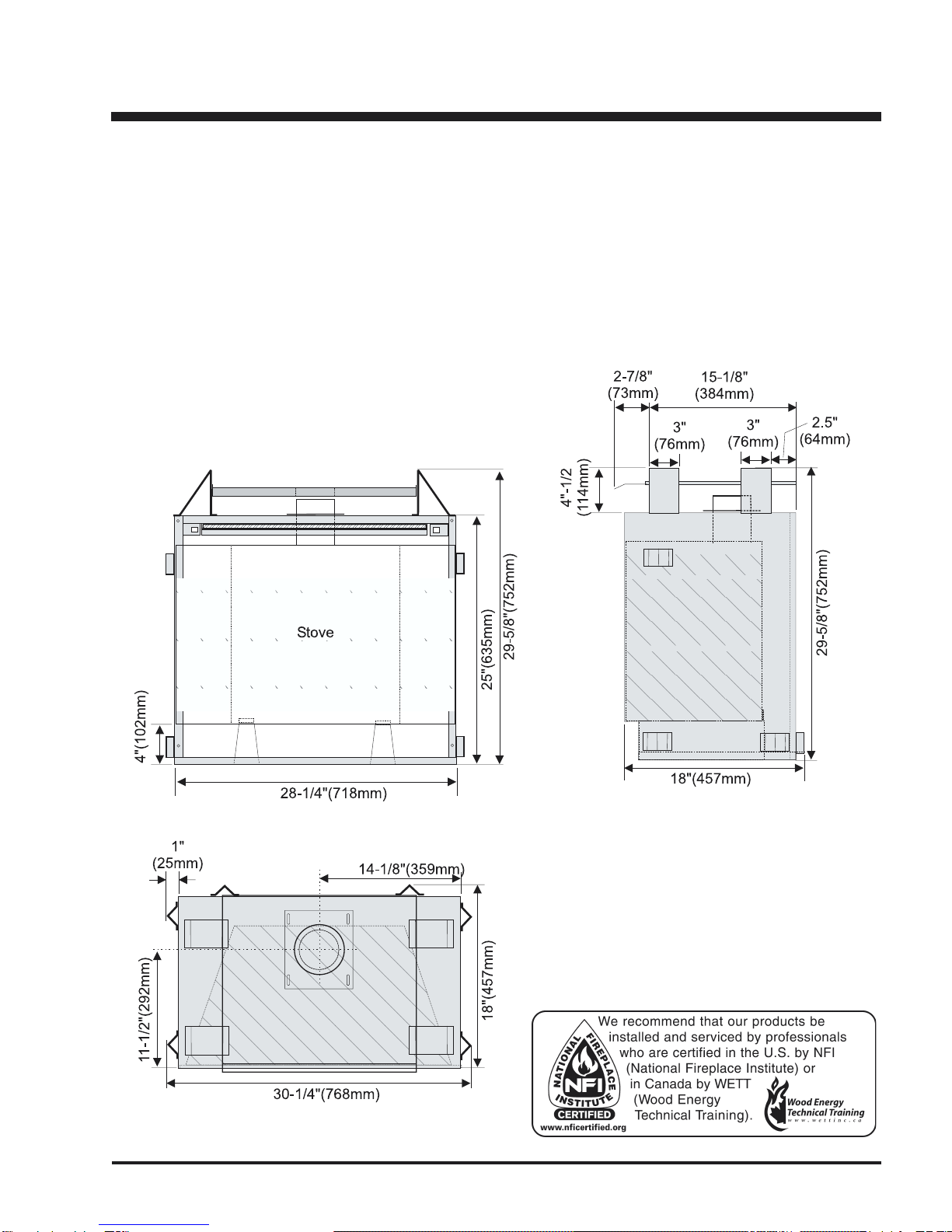
INSTALLATION
GENERAL INFORMATION
This kit consists of factory built parts that require minimal
assembly to form the Zero Clearance box for the U20/E21
GasInsert.TheZeroClearanceboxcanthenbefixedintoa
framed combustible construction, and a standard "B-vent"
installed on the assembly for the required venting. The
insert can be installed later. The faceplate will normally
overlapon topof thefinished wall. UsingKit# 530-936 you
can convert the U20/E21 Gas Insert models into highly
efficientheatproducingZeroClearanceFireplaces.
CLEARANCESTOCOMBUSTIBLES
The clearances for the Zero Clearance Kit are 0" to combustibles (back, side and floor) but when planning your
installation review the clearances required for the Insert (see below) after it is installed in the Zero Clearance Kit.
Clearances to Combustibles for Insert
The minimum clearance from the side of the appliance
to a combustible side wall is 9 inches (229mm). See the
"Mantel Clearances" chart (Diagram 2) for the minimum
clearance from the bottom of the Top Faceplate to a
combustible mantel. The minimum height from the
bottom of the Top Faceplate to the ceiling is 36 inches
(914mm). See diagram 1.
Diagram 2: Mantel can be installed anywhere in the
shaded area or higher. Use the grid to determine
height and depth of mantle.
Example: a 6" deep mantle must be 9" above the
bottom of the top faceplate.
Note: A non-combustible mantel may be installed
atalowerheightiftheframingismadeofmetalstuds
covered with a non-combustible board.
Note:Ensurethepaintthatisusedonthemantelandthe
facing is "heat resistant" or the paint may discolour.
Diagram1
Diagram2
TheZeroClearanceKit
must be installed on a
flat, solid, continuous
surface (e.g. wood,
metal, concrete). This
may be the floor, or
raiseduponaplatform
to enhance its visual
impact.
NOTE: The specified '0' inch floor clearance means that
thetopsurfaceoftheflooringmaterial,i.e.carpeting,tile,
etc., must not extend above the bottom edge of the 4"
Hearth Trim.