
REHM SYNERGIC.PRO 251 Come usare

D
GB
F
I
E
RUS
NL
HU
REHM SCHWEISSTECHNIKREHM SCHWEISSTECHNIK
SHORT MANUAL
SYNERGIC.PRO
251, 311, 351, 352, 402, 304, 404, 504
This short manual does not substitute the original operator manual.
Please read this document carefully before your start operating the welding power source.

This models of welding power sources have been developed according to the generally
recognized rules of technology. Nevertheless, their use can lead to a risk for life and limb
of the user or third pares or might lead to damages of the system or other property.
You should therefore read this document completely and thoroughly before starng up
the welding machine.
• Safety and warning noces are used for occupaonal safety and accident prevenon.
They must be observed. Not only the general safety instrucons listed here must be
observed but also the safety and warning informaon in the original manual.
• In addion to the informaon in these brief instrucons, the general safety and
accident prevenon regulaons have to be considered. They dier from country to
country (German: UVV BGV A3, TRBS 2131, BGR 500 Chapter 2.26 „Welding, cung
and allied processes“). In addion the specic regulaons for welding are relevant.
• Please nofy also the safety informaon signs in this document.
• As a maer of principle, no safety devices may be dismantled or put out of operaon,
as this poses a risk and the intended use of the system is no longer guaranteed.
Dismantling of safety devices when seng up, repairing and maintaining is specially
described. The safety devices must be reassembled immediately aer this work has
been completed.
• Changes to the system, the aachment or installaon of addional equipment and
external the use of safety devices is not permied. This invalidates the guarantee and
the reliability claim.
• If external agents are used (e.g. solvents for cleaning), the operator of the system must
guarantee the safety of the system during use.
• Except when this is expressly stated in wring by REHM, REHM welding systems are
only intended for sale to commercial / industrial users and only for their use.
The MIG/MAG welding systems are designed according to EN 60974-1 arc welding
equipment - welding power sources for overvoltage category III and polluon degree 3
and according to EN 60974-10 arc welding equipment - electromagnec compability
(EMC) for group 2 class A and are suitable for use in all areas , except residenal areas
that are directly connected to a public low-voltage supply system. Both conducted and
radiated interference can make it dicult to ensure electromagnec compability in
these areas. For this purpose, the observance of suitable measures to meet the require-
ments (lters for mains connecon, shielding such as the use of shielded lines, welding
lines that are as short as possible, earthing of the workpiece, equipotenal bonding) as
well as the assessment of the environment (such as computers, control equipment,
sound and television broadcast transmiers, neighboring Persons, e.g. when using a
pacemaker). The user is responsible for faults.
Qualicaon of the operang personnel
REHM welding systems may only be used by persons who are trained in the use,
operang and maintenance of the welding systems.
Only qualied, authorized and instructed personnel may work on and with the systems.
1 Safety Instructions

Symbols and sign at the welding machine or system
Aenon - danger or damage
Aenon - high voltage
Disregarding might cause injure or dead.
Personal protective equipment (PPE)
Personal protecve equipment (PPE) is mandatory when working with a welding system:
• Welding protecon lter, protecon level 10-15
• Protecve shield, screen or hood
• Welding gloves
• Leather apron
The company is obliged to provide the operator with the necessary PPE.
Intended Use
The MIG / MAG welding systems are only to be used
• for MIG / MAG or manual electrode welding for hand-guided and machine-guided
operaon (see original operang instrucons)
• for welding metallic materials (such as steels, copper, tanium and aluminum)
• in a perfectly safe condion
Environmental condions
• Temperature range of the ambient air:
- In operaon: -10 ° C to + 40 ° C (14 ° F to 104 ° F)
- During transport and storage: -20 ° C to + 55 ° C (-4 ° F to 131 ° F)
• Relave humidity
- up to 50% at 40 ° C (104 ° F)
- up to 90% at 20 ° C (68 ° F)
• Ambient air:
Free of unusual amounts of dust, acids, corrosive gases or substances, etc.
as long as these do not arise during welding.
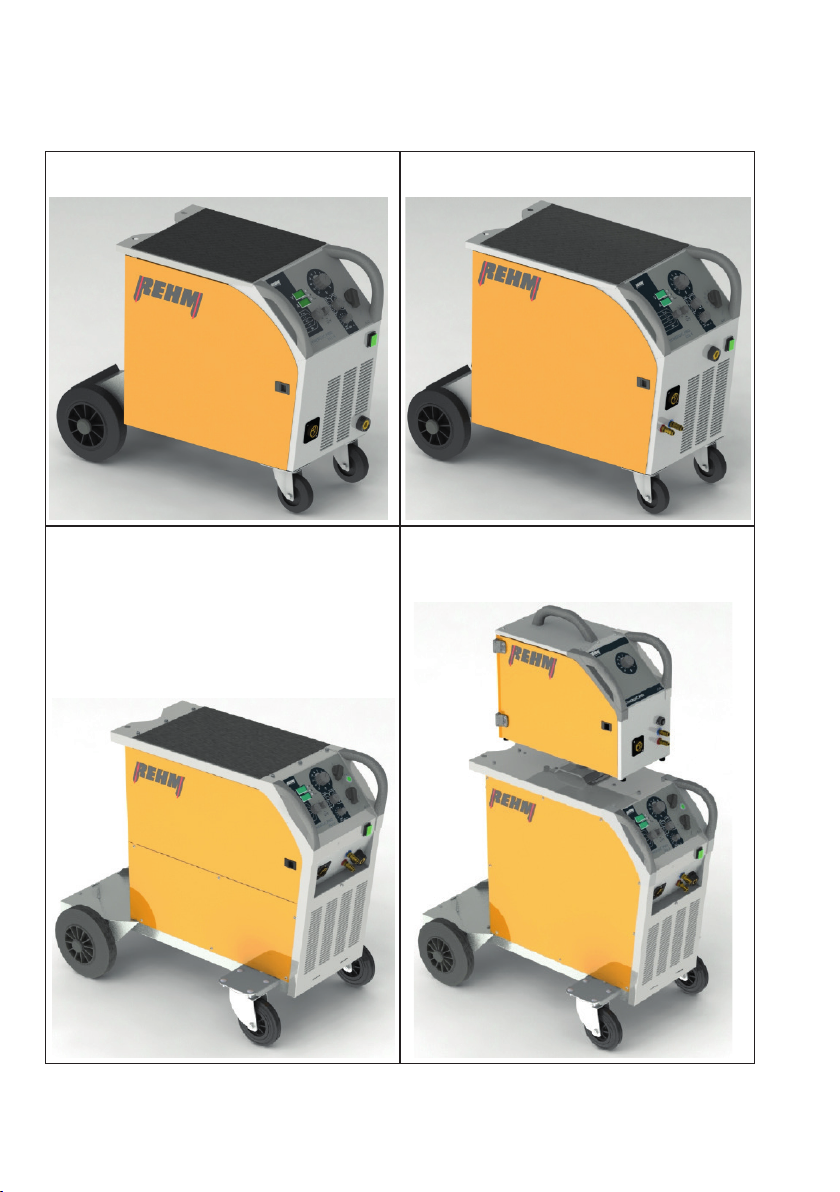
2 Design and Connecons
Compact welding machine 251, 311, 351
Compact machine 352, 402
Compact machine 304, 404, 504
Welding machine with separate wire feeder unit
304S, 404S, 504S

No. Detail
1Main switch
2 Central torch adapter (ZA)
3
Welding ground socket (-)
Aenon: Take care that there is a as short as possible and reliable connec-
on between machine and material. Otherwise current ow is uncontrolled
and is searching a path to potenal earth. Damages are possible.
4 Cooling water connecons (blue = Cold water; red = hot water)
5 Air entrance area for air cooling. Air exit area is on the rear side.
6HMI
7Access door to wire feeder unit
8 Place for the gas bole
9 Chain to secure the gas bole
1
2
3
4
5
6
7
8
9

3 HMI
Controls Funcons
1
2
3
4
5
6
7
89
11
12
10
13
1
Operaon
Boot 1.)
2.)
Inicaon of arc voltage
Indicaon of soware version e.g. P2.4
Indicaon of product version e.g. 404
2
Operaon
Boot 1.)
2.)
Indicaon of welding current or material thickness
Version of welding characterisc e.g.1.2
„on“ shows power source ready
3
Control LED „Operaon“ (grün)
Standby voltage is connected to the torch.
Arc ingnion will be acvated if wire touches material.
4
Control LED „Temperature“ (gelb)
If temperature gets too high the machine switches o the power to
protect internal power components. Cooling stays acve.
If temperature comes under a certain level, machine is reacvated
and LED switched o.
5
Control LED „7-Segment indicates material thickness“ (grün)
If switch (posion 7) is placed on the symbol the HMI on
7-segment indicator 2 shows material thickness. The value is related
to the machine adjustments you did. In that mode no welding is
possible.

Controls Funcon
6
Correkon of wire speed
Fine adjustment for wire speed in addion to the machine calculated
speed by adjustments of you did with the rotary cam switches 11 and
12. The correcon value stays acve even if you change steps.
Negave correcon = reduces wire speed => arc gets longer
Posive correcon = increases wire speed => arc gets shorter
If arc energie gets too low and welding result isn‘t convinient you
need to change output voltage by the rotary switches.
7
Mode switch
Auxiliary funcon to nd the right adjustment for a
certein material thickness. 7-Segment indicator 2.
For control reason value of calculated material thickness
is show shortly when acvang the torch buon.
If arc is astablished indicator show welding current.
2-Step mode
4-Step mode
Spot welding - me adjust with potenometer 8
Pulse welding - Interval welding
Pulse me can be adjusted with regulator 8,
the pause me is half the pulse me.
8Time seng
for funcons spot and pulse welding [0.1 ... 5.0 sec]
9
Material selecon switch
Selecon of material like aluminium, copper (CuSi3), steel and stain-
less steel (CrNi) and wire thickness like 0.8, 1.0, 1.2 mm
10
SDI adjustment
Stepless adjustable DC choke to allow hard or so welding arc.
If potenometer is in the le stop posion Automac SDI is switched
on. Now applicaon controller is calculang adjustment according to
posion of rotary switches.
11
Rotary cam switch - coarse adjustment
Not available in all products. Big increase of output voltage and
welding current.
12 Rotary cam switch - ne adjustment
Stepwise increase of voltage and current.
13
FOCUS switch
Arc will be focussed. Available only at products 304, 404 und 504 and
only for steel and stainless steel welding.

4 Automac Funcons
Funcon Descripon, Details
Creep automac Without acve arc, the control unit reduces wire speed
unl wire end touches material. With touch, ignion
starts automacally. Aer ignion, the automac system
accelerates the wire speed to setpoint.
Wire speed automac The synergic control unit calculates wire speed based on
the welding power set by the rotary switches 11, 12.
Fine adjustment is done with regulator 6.
Burn back
automac /
Free burn
automac
Intense of this automac funcon is to prevent wire
scks to material when welding is stopped.
The welding control unit calculates the me required to
avoid the wire scking in relaon to the actual wire
speed and braking phase.
Gas post-ow me The default value is 0,2 sec aer releasing torch trigger
buon.
Thread in automac With press and hold torch buon in 2 step mode, the
automac phase to thread the wire startes if system
detects no arc aer 3 sec.
Speed is set with regulator 6.
Welding stop automac The output voltage is automacally switched o in 4 step
mode if there is no current for 3 seconds.
Data hold automac Aer welding stop, the last current is stored and shown
in 7 segment display 2 (data hold).
SDI automac Steplessly controllable choke.
Acve if regulator 10 is in stop posion on the le side.
Water cooling All products with extension W are water cooled.
The cooling starts automacally with the welding and
stops with a delay me aer welding stop.
Gas ow test With the torch buon pressed and without an arc for 3
seconds, the gas valve opens automacally for maximum
25 seconds. It stops when the buon is released.

5 Special sengs (Specialists only)
Funcon Descripon, details
Specialists can use the
R59, R60 and R61 trim
resistors to change the
sengs for the following
funcons:
- Burn wire free me
- Creep speed
- Gas post-ow me

6 Wire feeder unit
Separate
feeder unit
for S Types
altern.
wire drive
unit is part
of the
compact
machine
Wire drive
unit
4/2
Wire feeder with 4 rolls. The rolls under the wire are driven, the rolls
on top of the wire are free running pinch rollers
1
Adjust contact pressure to the wire: Use the red screws.
- Unlock and lt pinch roller to the side of the door for threading wire
- Turn the screws le and right to ghten or loosen pinch roller.
Aenon:
When opening locks of pressure roller there is a risk of squeezing!
1
4
2
3
56
Questo manuale è adatto per i seguenti modelli
7
Indice
Altri manuali REHM Sistema di saldatura

REHM
REHM BARRACUDA 45i Manuale utente

REHM
REHM TIG.STAR 170 DC Manuale utente

REHM
REHM FOCUS.ARC P Series Come usare

REHM
REHM TIGER 170 DC Manuale utente

REHM
REHM INVERTIG.PRO digital 240 DC, 240 AC/DC Manuale utente

REHM
REHM BOOSTER.PRO 250 Manuale utente

REHM
REHM BOOSTER2 130 Supplemento

REHM
REHM TIGER DIGITAL 230 AC/DC ULTRA Manuale utente

REHM
REHM TIGER 180 AC/DC ULTRA Manuale utente

REHM
REHM SYNERGIC.ARC 251 Manuale utente


