RETRO 176 Manuale utente
Retro Instruments, Inc.
User’s Manual
176
Tube Limiting Amplifier

Retro Instruments, Inc.
176
Tube Limiting Amplifier
User’s Manual
2008 Retro Instruments, Inc.
P.O. ox 5066
Modesto, CA 95352-5066 USA
(209) 810-3344

Manual Revisions
Revision Print Date
Initial Release December 29, 2008
Notices
2008 Retro Instruments, Inc.
All rights reserved. No part o this document may be reproduced, transmitted,
transcribed, stored in a retrieval system, or translated into any language in any orm by
any means without the written authorization o Retro Instruments, Inc.
Printed in U.S.A.
User Manual Part Number – 176001-01
XLR, RCA, Xcelite, UA are trademarks o their respective companies.
Retro attempts to provide in ormation that is accurate, complete and use ul. I you
require urther in ormation or ind discrepancies in the text within, please contact Retro
Instruments.
Retro Instruments, Inc.
P.O. Box 5066
Modesto, CA 95352-5066 USA
(209) 810-3344

Contents
Section 1 Description
1.1 Your Limiter
1.2 Applications
1.3 Speci ications
1.4 Sa ety Considerations
Section 2 Installation
2.1 Operating Environment
2.2 Power Connections
2.2.1 AC Line Voltage Selection
2.2.2 Fuse
2.2.3 Line Cord
2.3 Input Connection
2.4 Output Connection
2.5 Stereo Link
2.6 Grounding
Section 3 Operation
3.1 Power Switch, Indicators and Interlock
3.2 Ampli ier Active/Bypass Switch
3.3 Input Level Control
3.3 Output Level Control
3.4 Compression Ratio Control
3.5 Attack and Release Controls
3.6 Sidechain High Pass Filter
3.7 Asymmetry Switch
3.8 Meter Select Switch
3.9 Stereo Linked Operation
Section 4 Principles of Operation
4.1 Ampli ier Circuit Board
4.1.1 Input Trans ormer Stage
4.1.2 6BC8 Variable Gain Stage
4.1.3 Interstage Trans ormer
4.1.4 12AX7 and 12BH7 Ampli ier Stage
4.1.5 6AL5 Detector and Ratio Switch
4.1.6 Asymmetry Switch
4.1.7 Sidechain Highpass Filter
4.1.8 Output Attenuator

4.1.9 Test Facilities
4.2 Power Supply Circuit Board
4.2.1 Mains Input
4.2.2 Power Trans ormer
4.2.3 5Y3 High Voltage Recti ier
4.2.4 OB2 Gas Discharge Tube
4.2.5 Bleeder Resistor
Section 5 Alignment and Maintenance
5.1 Gain Reduction Meter Zero
5.2 Internal Balance Test Switch
5.3 Balancing the 6BC8 Gain Reduction Stage
5.4 Balancing the Ampli ier Stage
5.5 Noise and Distortion Tests
5.6 Frequency Response Tests
5.7 Hum and Microphonics
Section 6 Schematics and Drawings
6.1 Board Layouts and Schematics
6.2 Recall Sheet
Section 7 Support and Service
7.1 Service
7.2 Support
7.3 Replacement Parts
7.4 Warranty
7.5 Factory Service Instructions

Section 1 Description
This section provides a general description o the 176 Tube Limiting Ampli ier. Please
review this in ormation be ore installing or operating the 176.
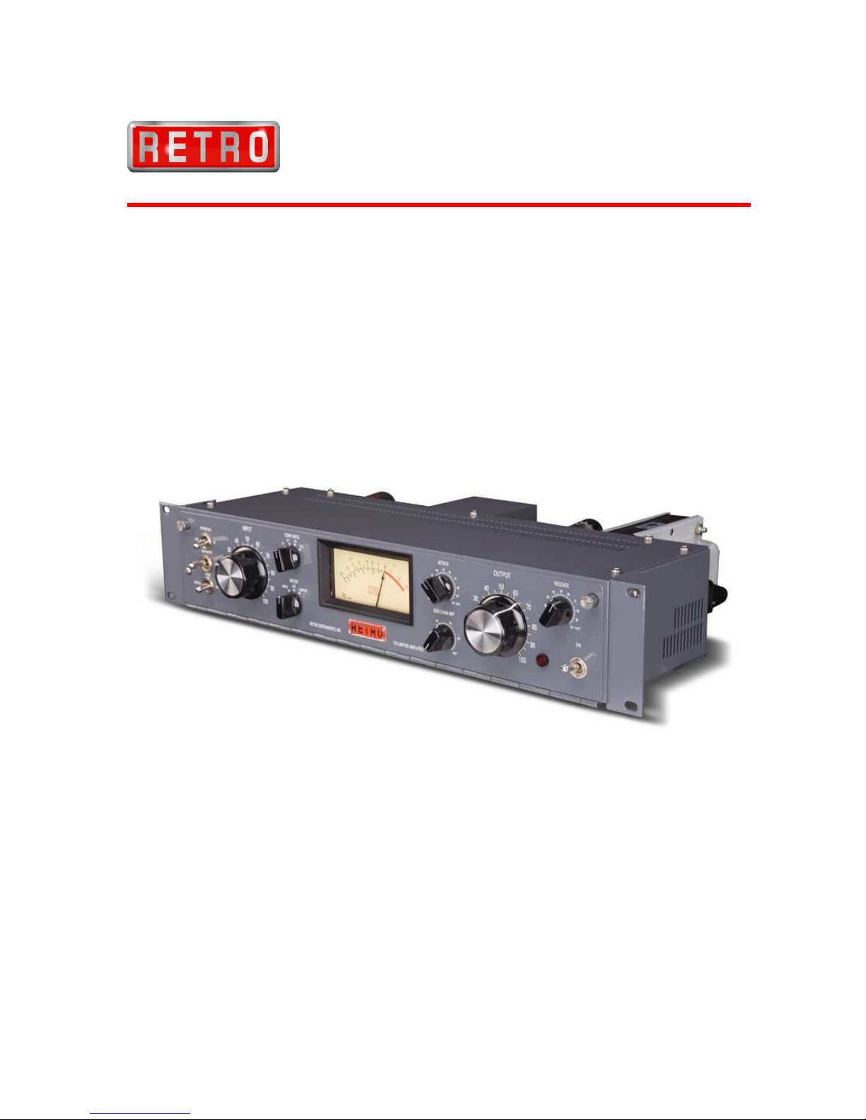
1.1 Your Limiter
The 176 Tube Limiting Ampli ier is designed to provide the quintessential character o
vintage tube compression in the modern recording studio environment. It is modeled
a ter the superb UA 176 limiter and adds new eatures and conveniences. The Retro 176
uses high quality components that should provide many years o trouble- ree service.
Your limiter has been through a ull burn-in and testing procedure at the actory.
Ease o use is key with user- riendly ront panel controls and easily recallable settings.
No matter what settings you use, the great sonic traits o the 176 will enhance your
recordings.
1.2 Applications
The Retro 176 is designed or great versatility in many applications. Because o the way
real tube compression handles dynamics, the 176 enhances dimension, depth and detail.
Independent tracks such as vocal, bass, acoustic guitar, piano ill out nicely without harsh
restraint. The 176 is great or tracking, mixing and multibuss compression applications.
Possibly the best application or the 176 is use on the stereo buss, bu ing it to a glossy
inish. The Retro 176 adjusts tone in a way that equalization cannot.
1.3 Specifications
Frequency Response Flat within 0.5 dB rom 20-20,000 Hz.
Harmonic Distortion Below 1% rom 20-20,000 Hz at 0-15 dB Gain Reduction
Noise Level Greater than 76 dB below normal operating level
Gain Reduction 20 dB o available gain reduction
Maximum Gain 32 dB with input and output controls set maximum
Input Impedance 600 Ohms - loating trans ormer balanced
Output Impedance 600 Ohms - loating trans ormer balanced
Minimum Input Level –26 dBm@2:1 ratio –12 dBm@12:1 ratio
Normal Operating Level +4 dBm
Maximum Operating Level +20 dBm
Maximum Operating Temp. 55° C
Physical Dimensions Standard 19” rack mounted. 2U, 3.5” high, 9.5” deep
Power Requirements 40 Watts at 115/230 VAC, 50/60 Hz.

1.5 Safety Considerations
The Retro 176 is to be used in a metal equipment rack with adequate ventilation. The
vacuum tubes become hot. The AC mains power should be disconnected prior to
servicing. For sa ety, the ront door o the 176 is equipped with an interlock switch that
interrupts the AC mains power when the door is opened. This switch should not be
de eated. Only trained technicians should open the ront door to gain access to the
internal adjustments. Tubes should not be removed or inserted with the power on. An
accidental breakage o the glass envelope can expose high voltage on the plate o the
tube.
This product is grounded through the AC Power Cord. For sa ety, do not li t or remove
the ground rom the AC Power Source.
Section 2 Installation
2.1 Operating Environment
Mount the 176 in a standard 19” equipment rack. Always install the bottom rack screws
irst to support the unit. Please allow room above the top ventilation holes and above the
tubes. Additionally, there are ventilation holes on the sides to draw in cool air. Be aware
o the heat sources in your rack to allow proper cooling. Heat will shorten the li e o
your equipment.
Audio equipment is sensitive to magnetic ields caused by nearby power supply
trans ormers. I you experience 60 Hz. hum in any o your gear, try unplugging adjacent
gear irst.
I you purchased a matched pair with the link panel, mount the panel between the two
units and connect the RCA cables to the Couple jack on each 176.
2.2 Power Connections
2.21 AC Line Voltage Selection
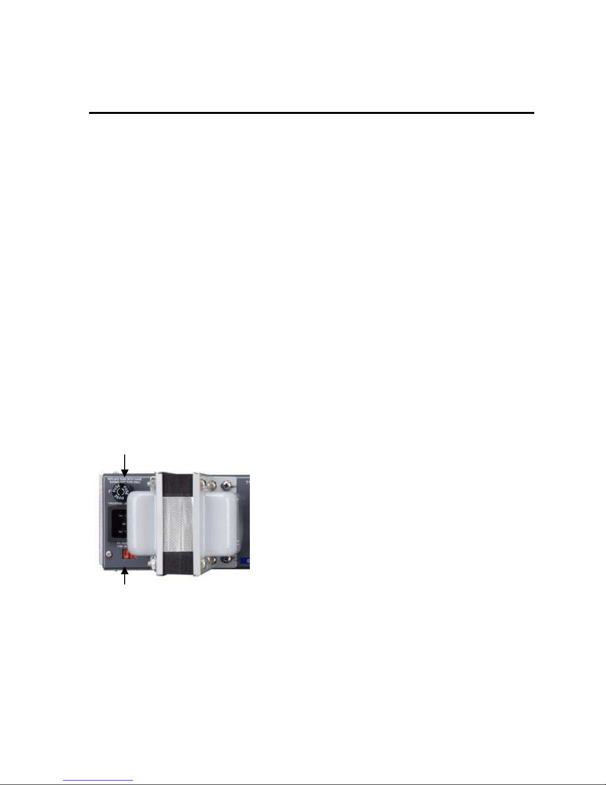
AC Mains Voltage is applied to the IEC standard AC receptacle on the rear o the unit.
Set the Red AC Voltage Selector switch on the rear o the unit to 115 or 230 Volts or
your mains voltage. You can use a small lat screwdriver.
Power Fuse
Voltage Selector
2.2.2 Fuse
The use is a 1A ast blow 3AG type or 115 or 230 Volt Mains Voltage. Disconnect the
power cord be ore changing the use.
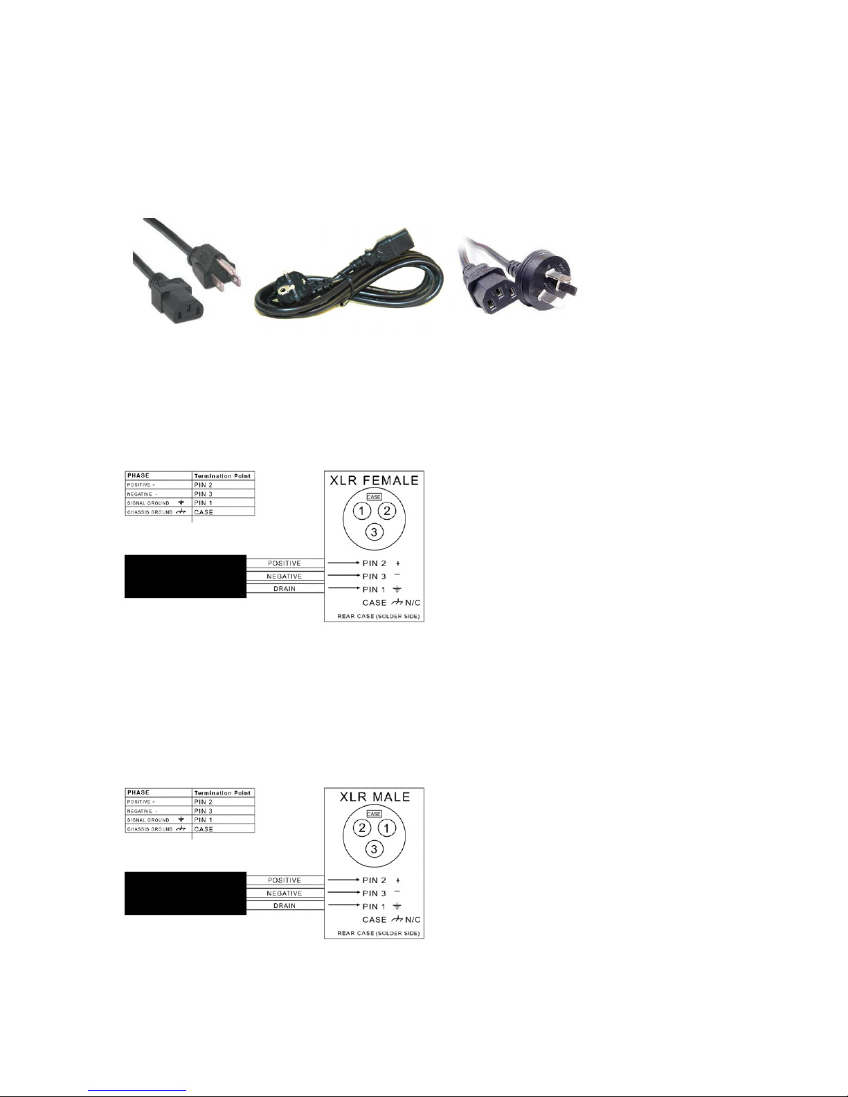
2.2.3 Line Cord
You can use a compatible IEC power cable or 100-120 Volts or 200-240 Volts per your
country’s speci ication.
USA Europe Australia
2.3 Input Connection
Audio Input is a standard emale XLR connector. It is trans ormer balanced and loating,
meaning there is no path to ground rom pin 2 and 3. Unbalanced sources connect the
center conductor to pin 2 and the shield to pin 3.
2.4 Output Connection
Audio Output is a standard Male XLR connector. It is trans ormer balanced and loating,
meaning there is no path to ground rom pin 2 and 3. Unbalanced loads connect the
center conductor to pin 2 and the shield to pin 3.
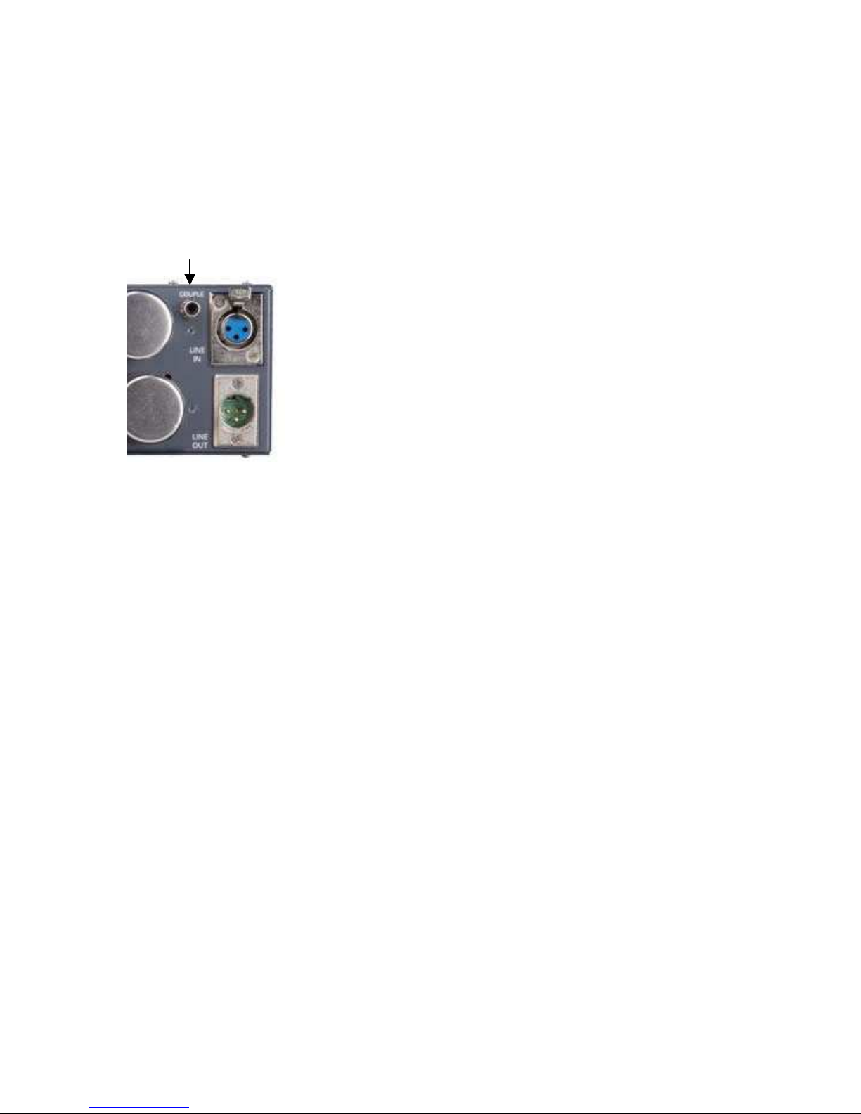
2.5 Stereo Link
An RCA jack on the rear panel allows strapping o multiple 176 limiters. An optional
stereo link panel is available to couple two units.
Coupling Jack
2.6 Grounding
The 176 is primarily grounded through the AC Mains. For sa ety, do not disable the AC
ground. The chassis is also grounded through the rack ears to the rack. The XLR
connectors are grounded on pin 1. Pin 1 is only used to drain the shield o the audio
cable on one end o the cable. The exception to the rule is a microphone cable, where pin
1 is used to carry ground to the microphone case.
Indice


