RetroRadionics ArcadeR Manuale utente
User Guide V1.2

What is the ArcadeR?
The ArcadeR is a joystick from RetroRadionics, designed for
classic computers that use the Atari 9-pin connector that was
popular from the late 70’s until the mid 90’s. It’s built using
high quality arcade components; the stick is based on the
poplar Sanwa JLF and is compatible with after-market
accessories including restrictor gates, springs, actuators and
handles.
The ArcadeR features autofire on the primary fire button, and
the option to reconfigure the secondary fire button.
Primary fire
button
Secondary
fire button
Feature
button 1
Feature
button 2

What’s in the box?
Included in every box will be:
•ArcadeR joystick
•Domed dust cover
•Ball top
More recent shipments also include:
•Neoprene shaft cover
•Rubber washer to hold the dust cover down
•Additional wiring harnesses.
NOTE: Some ArcadeR’s may be shipped with a second restrictor gate. See the
F.A.Q. for more details
Setting up the ArcadeR
To set up the ArcadeR for the first time, place the domed dust
cover over the stick shaft. You may also, if included fit the
rubber washer above the dust cover, and the neoprene shaft
cover. Finally screw on the ball top. If no washer is used, then
the dust cover will freely move around –this is normal.
Holding the joystick shaft while turning the ball top finger tight
should be enough to keep it in place, however there is also a
slot cut into the bottom of the joystick shaft. You can use a
screwdriver to brace the stick shaft when fitting the ball,
enabling it to be tightened further.

This requires the removal of the three screws at the base of the
ArcadeR in order to open the case and gain access to the
bottom of the stick mechanism.

Using the ArcadeR (without modification)
Straight out of the box, the ArcadeR is designed to work with 8
and 16 bit computers that used a regular 9-pin Atari-style
joystick port.
This includes:
•Amstrad CPC machines
•Atari 8-bit machines (VCS/2600, 400, 800, XL and XE series)
•Atari 16-bit machines (ST, TT, Falcon)
•Commodore 64 and 128
•Commodore Amiga machines
•MSX
•ZX Spectrum –via Dims/Kempston interface
•ZX Spectrum Next
•FPGA computers including MiST and Mistica
•Mister FPGA computer via various DE9-USB adaptors
For some machines, only Button 1 may work. This depends on
both the machine in question (some only support a single fire
button) and the software being loaded.
Feature button 1 toggles autofire on the primary fire button.
Feature button 2 alternates the function of the secondary fire
button between Fire 2 and Fire 3 for systems that recognise
more than one fire button.

The ArcadeR circuit board
There are currently two versions of the circuit board used in the
ArcadeR, version 1.5b and 1.5c. In some cases, making
modifications to your joystick may require making changes to
the circuit board itself. The pictures below show the location of
key parts of the ArcadeR board.
PCB 1.5b
PCB 1.5c

Modifying the ArcadeR
The ArcadeR is designed to be customisable and allows several
changes to be easily made. In order to access the circuit board,
remove the three screws at the bottom of the ArcadeR, and
gently pull the two halves of the shell apart. All the
components of the joystick (the stick mechanism, the buttons
and the cable) can be unplugged from the circuit board.
Many modifications have been published on the ArcadeR
Facebook page. A number are included below:
•Swap Button 1 and Button 2 (for left-handed use)
oSimply change the position of where the wires for
Button 1 and Button 2 connect to the circuit board.
•Enable autofire on the ZX Next, MSX and Sega Master
System
oFor PCB version 1.5b:
▪To enable this function, pins 5 and 7 of the 9-pin
cable need to be swapped around. This will
require access to the underside of the circuit
board, so remove the two screws holding the
board to the base of the case.
▪Disconnect the 9-pin cable from the circuit
board.
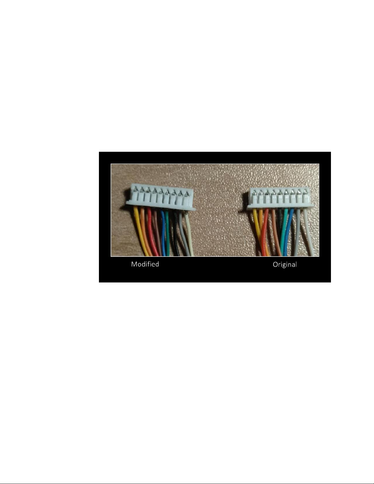
▪Using a needle, lever up the plastic pins of the 9-
pin connector that hold pin 5 and 7 in place,
while simultaneously pulling the wire out.
•Note: working from left to right (with the
yellow pin 1 on the left), pin 5 is black and
pin 7 is blue.
▪Push the wires into their new positions, with
blue now in position 5, and black in 7.
oFor PCB version 1.5c:
▪Disconnect the 9-pin cable from the “VCC on 7”
port of the circuit board and reconnect to “VCC
on 5”
oNOTE: This modification will also allow limited
compatibility with the Sega Mega Drive.

•Enable the secondary fire button on the Commodore 64
oFor PCB version 1.5b:
▪PCB 1.5b has a 3-way solder pad above the 9-pin
cable connector. By default, this is bridged
between the centre and lower pads (Atari
mode). By removing the solder bridge and
instead bridging the centre and upper pad, the
second fire button is enabled for C64 and MSX
computers (for supported software).
▪Next to the solder bridges are three through-
holes. It’s possible to solder pin headers here,
and after removing the solder bridge, use a
jumper instead.
oFor PCB version 1.5c:
▪Remove the circuit board from the ArcadeR to
access the underside.
▪Swap the jumper J1 from the middle-lower pins
to the middle-upper pins.
oNote: This modification is only necessary to utilise the
secondary fire button. The primary fire button will
still work regardless of the jumper position.

•Enable the secondary fire button on Commodore Amiga
computers if not automatically recognised
oThe value of the surface mount resistor (R1) in the
ArcadeR has too high a value for some Amiga
computers to recognise the additional fire signals.
oFor PCB version 1.5b, removal of this resistor and
replacing with wire, or a 0-ohm resistor will enable
the ArcadeR secondary fire button to work with an
Amiga.
oPCB version 1.5c has a jumper on the underside of
the board to bridge R1.
▪Remove the circuit board from the ArcadeR to
access the underside.
▪Install a jumper across the two-pin connection.
oNote: This modification is only necessary to utilise the
secondary fire button.
oIMPORTANT NOTE: bridging resistor R1 as mentioned
above is for the Amiga ONLY. Using an ArcadeR with
this modification on any other type of machine can
cause damage to that device.
Indice


