RFC SL Series Manuale utente

SL series screw refrigeration compressor
technical manual
Zhejiang Daming Refrigeration Technology Co., Ltd.

Table of contents
1. Summary 01
1.1 Product introduction 01
1.2 model name 01
1.3 Product Series 01
1.4 Introduction 02
1.5 design specification 02
1.6 Operating Range Chart 03
2. Refrigerated Oil Management 05
2.1 The role of refrigeration oil in the press knitting machine 05
2.2 S1 compressor specified refrigeration oil 05
2.3 Refrigerant oil replacement requirements 05
2.4 External oil circuit system 06
3. Start, stop and capacity control 06
3.1 Cooling capacity control06
3.2 Efficiency at Partial Load and Considerations07
3.3 Compressor start and stop 07
4. Electrical articles 08
4.1 motor08
4.2 protective device 09

4.3 Power supply 10
4.4 Electrical accessories selection 10
5. Main accessories and accessories 11
5.1 Suction filter 11
5.2 one-way valve 11
5.3 Rubber damping pad 11
5.4 Accessories in the oil circulation circuit 12
6. Outline 15
6.1 RFC1 series outline drawing 15
6.2 RFC2 series outline drawing 16
6.3 RFC3 series outline drawing 17
6.4 RFC4 series outline drawing 18
6.5 RFC5 series outline drawing 19
7. system applications 20
7.1 Overview 20
7.2 general principles 20
7.3 External oil circuit system 22
7.4 Economizer Configuration Requirements 23
7.5 Condensing pressure regulation 24
7.6 Parallel system operation requirements 24

8. Install and run 25
8.1 Install 25
8.2 run 25
9 Failure analysis and maintenance 27
9.1 General fault description 27
9.2 maintenance 28
9.3 Maintenance points 28

1. Summary
1. 1 Product introduction:
SLG&SLD series products are low-temperature special screw refrigeration compressors
carefully developed by RFC in recent years to integrate low-temperature refrigeration market
applications and customer needs, and learn from the experience of domestic and foreign
counterparts. The product is designed with excellent performance, simple structure and
convenient use. It focuses on the application needs of the low temperature market and is
widely used in agriculture, fishing, meat, food industry, process cooling, freeze drying and
other industries.
There are 32 models of SLG&SLD semi-hermetic screw compressors. SL series
compressors from 30HP to 300HP (displacement volume at 50Hz: 102, 128, 145, 158, 188,
205, 235, 248, 293, 354, 416, 520, 641, 812, 908, 1006m³ /h), each type of compressor has
two different built-in volume ratios, which are suitable for occasions with low evaporating
temperature and medium and high evaporating temperature respectively. Therefore, the user
can choose the ideal compressor according to the actual application, so as to obtain the best
compression efficiency.
SL series compressors all use external oil separators. The use of external oil separators
can provide greater flexibility in design and structural arrangement. In the parallel combination
system of multiple compressors (from 2 to 6 units) ) can only use a common oil separator. In
addition, the use of oil cooling has broadened the compressor application limits so that it can
operate under harsh operating conditions.
A complete set of accessories required for the oil return line (from the oil separator to the
compressor) is available as standard. In addition all matching oil separators and oil coolers are
also available.
Due to the minimal vibration and no exhaust pulsation, the use of shock absorbers and
flexible nozzles is not necessary. Plus, the lower noise concentrated in the mid-to-high
frequencies is very easy to isolate.
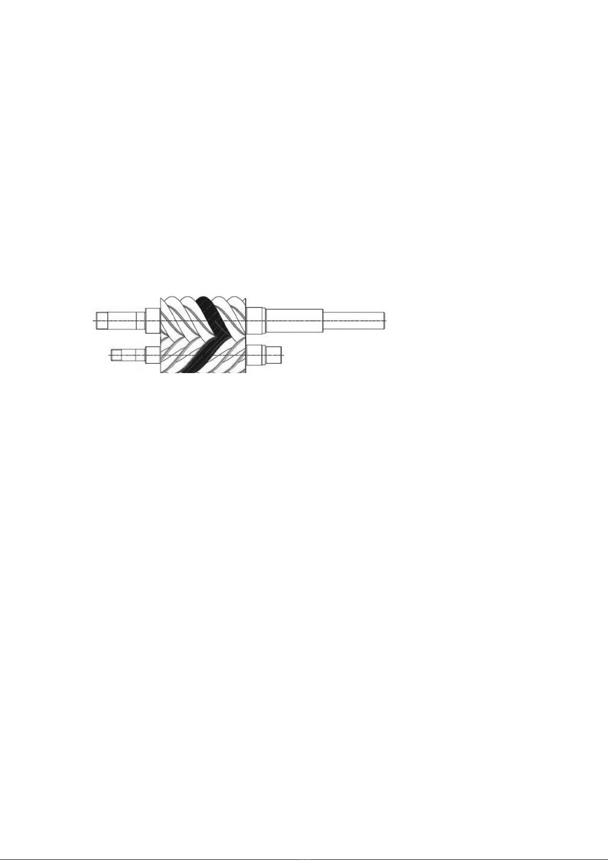
The characteristics of SL series compressors are: the oil-injected twin-screw design is
adopted, the male rotor is directly connected to the motor (2 poles, about 2960 rpm), and the
perfect rotational motion makes it run extremely smoothly. The rotor profile is asymmetrically
designed (the number of teeth of the male rotor is 5, and the number of teeth of the female
rotor is 6). .
Oil pressure driven spool valve cooling capacity control enables the compressor to have
high compression efficiency under partial load, making SL series compressors especially
suitable for those occasions that need to work under partial load for a long time.
The cycle efficiency (COP) can be further achieved by using an economizer (ECO) cycle
that increases the refrigerant liquid subcooling

1.2 model nomenclature
S Semi-hermetic
L Refrigeration
D D: low temperature G: high temperature
210 Displacement (m3/h)
60 Motor nominal power (HP)
Y Step adjustment (Step Control)
D Single stage compression (single stage)
1 Version
Refrigeration Displacement (m3/h)
S L D 210 -60 Y D 1
Semi-hermetic low temperature Motor nominal power (HP)
Compressor rated power: 380V-3-50HZ, if customers need other special voltage and
frequency, please contact RFC.
1.3 Product Series
SL series compressor displacement specification table
Figure 1-A SL series compressor displacement specification table

1.4 Introduction
The rotors are located in a horizontally arranged compression chamber with a suction port
(on the motor side) and a discharge port, with extremely small gaps between the rotors and
between the rotors and the housing by means of direct injection onto the rotor profile. The oil
film formed by the lubricating oil performs dynamic sealing. The formation of the compression
process is that the motor drives the rotor to rotate, causing the volume to gradually decrease;
the multiple compression chambers formed between the rotor and the casing due to the
rotation of the rotor move along the axial direction of the rotor while the volume gradually
decreases. Small.
The basic process of compression can be divided into three stages: suction,
compression and exhaust
Figure 1-B Compression principle of screw compressor

1.5 design specification
model
Exhaust
volume
50Hz
Motor
nominal
power
Weight
exhaust
pipe
diameter
Suction
pipe
diameter
ability
adjustm
ent
protection
module
Standar
d Motor
star/delta
starting
current
Maximu
m
operating
current
m'/h Hp/Kw Kg mm mm A A
SLD100-25 102 30/22 245
45 57
50% ,
70% ,
100
adjust INT 69
380V/3/
50Hz-
460V/
3/60HZ
131 42
SLG100-35 40/30 255 134 56
SLD120-30 128 30/22 245 131 42
SLG120-40 40/30 255 134 56
SLD140-40 145 40/30 255 134 63
SLG140-50 50/37 275 139 78
SLD160-50 158 50/37 260 179 75
SLG160-60 60/45 280 182 85
SLD190-50 188 60/45 405
57 76
182 90
SLG190-65 70/52 430 193 104
SLD210-60 205 60/45 410 182 95
SLG210-70 70/52 440 195 108
SLD230-70 235 70/52 420 193 112
SLG230-80 80/60 450 298 126
SLD250-75 248 75/57 430 230 118
SLG250-90 90/68 460 318 144
SLD290-80 293 80/60 535
67 89
298 126
SLG290-100 100/75 570 338 158
SLD350-100 354 100/75 545 338 157
SLG350-120 120/89 590 366 187
SLD420-125 416 120/89 670 76 89 416 187
SLG420-150 145/108 690 453 228
SLD520-160 520 160/120 1030
89 108
25% ,
50% ,
75%,
100
543 251
SLG520-180 180/135 1060 595 284
SLD640-200
641
200/143 1050 678 301
SLG640-220 210/157 1090 767 331
Note: Please confirm the rated current of the compressor under the design conditions
according to the RFC selection procedure, and confirm the maximum operating current value
according to the limit conditions to select the contactor, power cord and fuse protection
components。

1. 6 Operating Range Chart
SLD series R22
Evaporation temperature °C
SLG series R22
Evaporation temperature °C
Condensin
g
tem
p
erature°C Condensingtemperature°C

SLD series R404A/R507
Evaporation temperature °C
SLD series R404A/R507
Evaporation temperature °C
Condensing temperature°CCondensing temperature °C
Questo manuale è adatto per i seguenti modelli
26
Indice


