Rice Lake SENDit Manuale utente

SENDit™
Wireless Load Cell Interface
Installation Manual
PN 167466 Rev FOctober 24, 2019

An ISO 9001 registered company
© Rice Lake Weighing Systems. All rights reserved.
Rice Lake Weighing Systems® is a registered trademark of
Rice Lake Weighing Systems.
All other brand or product names within this publication are trademarks or
registered trademarks of their respective companies.
All information contained within this publication is, to the best of our knowledge, complete and
accurate at the time of publication. Rice Lake Weighing Systems reserves the right to make
changes to the technology, features, specifications and design of the equipment without notice.
The most current version of this publication, software, firmware and all other product
updates can be found on our website:
www.ricelake.com

Contents
© Rice Lake Weighing Systems ● All Rights Reserved i
Contents
Technical training seminars are available through Rice Lake Weighing Systems.
Course descriptions and dates can be viewed at www.ricelake.com/training
or obtained by calling 715-234-9171 and asking for the training department.
1.0 Introduction . . . . . . . . . . . . . . . . . . . . . . . . . . . . . . . . . . . . . . . . . . . . . . . . . . . . . . . . . . . . . . . . . . . . . . . . . . . . 1
1.1 Safety . . . . . . . . . . . . . . . . . . . . . . . . . . . . . . . . . . . . . . . . . . . . . . . . . . . . . . . . . . . . . . . . . . . . . . . . . . . . . . . . . . . . . . . . . . . . . 1
1.2 Options . . . . . . . . . . . . . . . . . . . . . . . . . . . . . . . . . . . . . . . . . . . . . . . . . . . . . . . . . . . . . . . . . . . . . . . . . . . . . . . . . . . . . . . . . . . . 2
1.3 Overview . . . . . . . . . . . . . . . . . . . . . . . . . . . . . . . . . . . . . . . . . . . . . . . . . . . . . . . . . . . . . . . . . . . . . . . . . . . . . . . . . . . . . . . . . . . 3
1.4 Front Panel . . . . . . . . . . . . . . . . . . . . . . . . . . . . . . . . . . . . . . . . . . . . . . . . . . . . . . . . . . . . . . . . . . . . . . . . . . . . . . . . . . . . . . . . . 4
2.0 Installation . . . . . . . . . . . . . . . . . . . . . . . . . . . . . . . . . . . . . . . . . . . . . . . . . . . . . . . . . . . . . . . . . . . . . . . . . . . . . 5
2.1 Unpacking and Assembly . . . . . . . . . . . . . . . . . . . . . . . . . . . . . . . . . . . . . . . . . . . . . . . . . . . . . . . . . . . . . . . . . . . . . . . . . . . . . . 5
2.2 Mounting the Enclosure . . . . . . . . . . . . . . . . . . . . . . . . . . . . . . . . . . . . . . . . . . . . . . . . . . . . . . . . . . . . . . . . . . . . . . . . . . . . . . . 5
2.3 Cable Connections . . . . . . . . . . . . . . . . . . . . . . . . . . . . . . . . . . . . . . . . . . . . . . . . . . . . . . . . . . . . . . . . . . . . . . . . . . . . . . . . . . . 6
2.3.1 Connect Transmitter. . . . . . . . . . . . . . . . . . . . . . . . . . . . . . . . . . . . . . . . . . . . . . . . . . . . . . . . . . . . . . . . . . . . . . . . . . . 6
2.3.2 Connect Receiver. . . . . . . . . . . . . . . . . . . . . . . . . . . . . . . . . . . . . . . . . . . . . . . . . . . . . . . . . . . . . . . . . . . . . . . . . . . . . 6
3.0 RF Pairing. . . . . . . . . . . . . . . . . . . . . . . . . . . . . . . . . . . . . . . . . . . . . . . . . . . . . . . . . . . . . . . . . . . . . . . . . . . . . . 7
3.1 Pairing Receivers and Transmitters . . . . . . . . . . . . . . . . . . . . . . . . . . . . . . . . . . . . . . . . . . . . . . . . . . . . . . . . . . . . . . . . . . . . . . 7
4.0 Calibration . . . . . . . . . . . . . . . . . . . . . . . . . . . . . . . . . . . . . . . . . . . . . . . . . . . . . . . . . . . . . . . . . . . . . . . . . . . . . 9
5.0 Appendix . . . . . . . . . . . . . . . . . . . . . . . . . . . . . . . . . . . . . . . . . . . . . . . . . . . . . . . . . . . . . . . . . . . . . . . . . . . . . 12
5.1 Antenna Options . . . . . . . . . . . . . . . . . . . . . . . . . . . . . . . . . . . . . . . . . . . . . . . . . . . . . . . . . . . . . . . . . . . . . . . . . . . . . . . . . . . . 12
5.1.1 Standard Antenna . . . . . . . . . . . . . . . . . . . . . . . . . . . . . . . . . . . . . . . . . . . . . . . . . . . . . . . . . . . . . . . . . . . . . . . . . . . 13
5.1.2 Long Range OMNI 9 dBi Antenna . . . . . . . . . . . . . . . . . . . . . . . . . . . . . . . . . . . . . . . . . . . . . . . . . . . . . . . . . . . . . . . 13
5.1.3 Vehicle Mount Whip Antenna. . . . . . . . . . . . . . . . . . . . . . . . . . . . . . . . . . . . . . . . . . . . . . . . . . . . . . . . . . . . . . . . . . . 13
5.1.4 YAGI Antenna . . . . . . . . . . . . . . . . . . . . . . . . . . . . . . . . . . . . . . . . . . . . . . . . . . . . . . . . . . . . . . . . . . . . . . . . . . . . . . 13
5.1.5 Corner Reflector Antenna . . . . . . . . . . . . . . . . . . . . . . . . . . . . . . . . . . . . . . . . . . . . . . . . . . . . . . . . . . . . . . . . . . . . . 13
5.1.6 Patch Antenna . . . . . . . . . . . . . . . . . . . . . . . . . . . . . . . . . . . . . . . . . . . . . . . . . . . . . . . . . . . . . . . . . . . . . . . . . . . . . . 13
6.0 Specifications . . . . . . . . . . . . . . . . . . . . . . . . . . . . . . . . . . . . . . . . . . . . . . . . . . . . . . . . . . . . . . . . . . . . . . . . . 14

© Rice Lake Weighing Systems ● All Rights Reserved 1
Introduction
1.0 Introduction
The SENDit Wireless Load Cell Interface transmitters and receivers are efficient communication devices that replace the need
for traditional wire runs. Compatible with a broad range of transmitting and receiving devices, SENDit is designed to work with
ScaleCore-based products as shown in Figure 1-1 on page 3. SENDit transmitters can interface with virtually any strain-gage
sensor. This manual provides the details for SENDit and SENDit installation, configuration and calibration.
Manuals and additional resources are available from the Rice Lake Weighing Systems website at www.ricelake.com
Warranty information can be found on the website at www.ricelake.com/warranties
1.1 Safety
Safety Signal Definitions:
Indicates an imminently hazardous situation that, if not avoided, will result in death or serious injury. Includes
hazards that are exposed when guards are removed.
Indicates a potentially hazardous situation that, if not avoided, could result in serious injury or death. Includes
hazards that are exposed when guards are removed.
Indicates a potentially hazardous situation that, if not avoided, could result in minor or moderate injury.
Indicates information about procedures that, if not observed, could result in damage to equipment or corruption
to and loss of data.
General Safety
Do not operate or work on this equipment unless this manual has been read and all instructions are understood.
Failure to follow the instructions or heed the warnings could result in injury or death. Contact any Rice Lake
Weighing Systems dealer for replacement manuals.
Failure to heed could result in serious injury or death.
Do not allow minors (children) or inexperienced persons to operate this unit.
Do not use this unit if any of the components are loose or cracked.
Do not remove or obscure warning labels.
Do not use near water.
Do not place fingers into slots or possible pinch points.
Do not make alterations or modifications to the unit.
There are no user serviceable parts within the SENDit units. Any repairs are to be performed by qualified service personnel only.
DANGER
WARNING
CAUTION
IMPORTANT
WARNING
SENDit Wireless Load Cell Interface
2 Visit our website www.RiceLake.com
1.2 Options
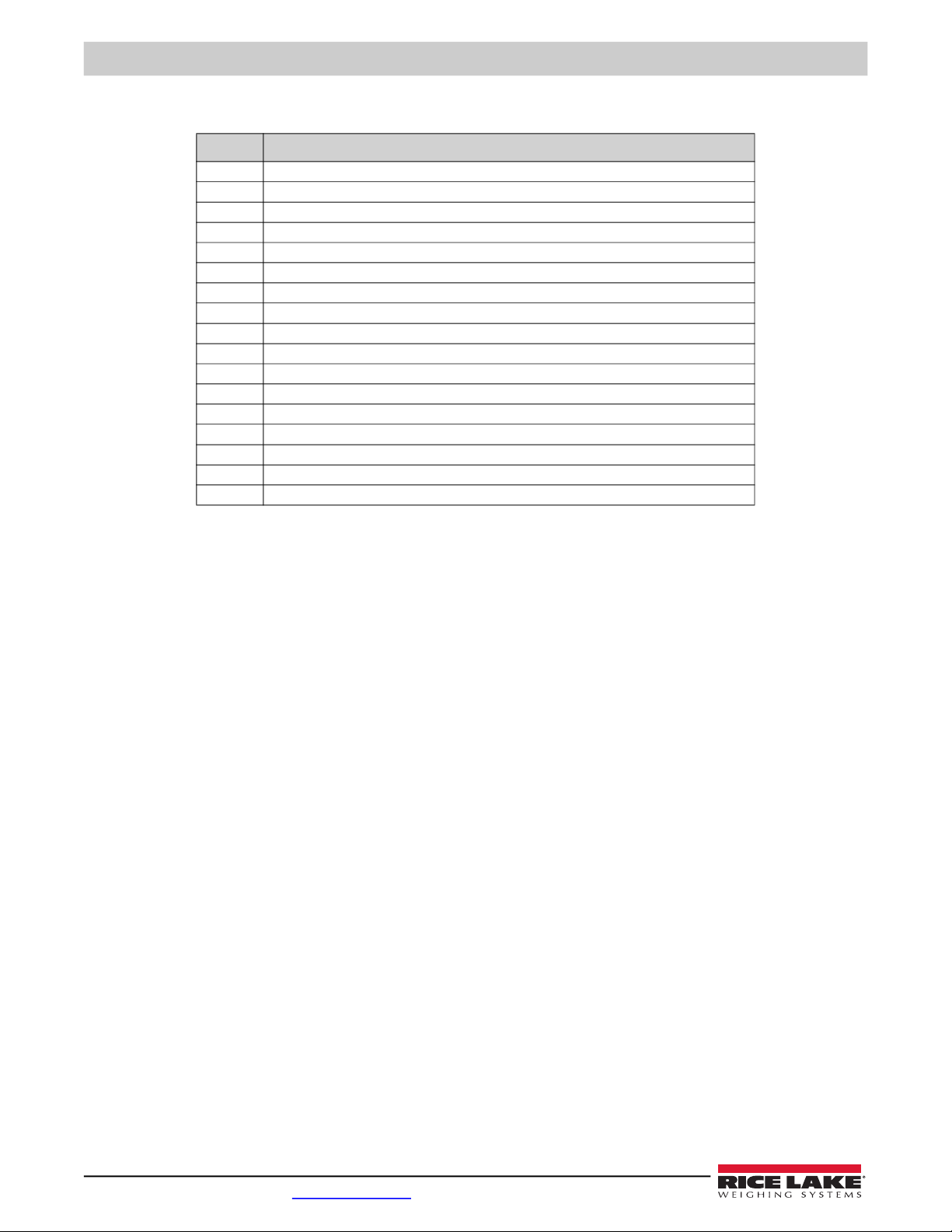
Part No Description
162172 Charger, SENDit for 6V SLA battery
162173 Battery, SENDit 6V SLA
162175 Enclosure, SENDit for 6V SLA battery
150964 RS-232 13' (4 m) serial cable with 9-Pin (female) connector
150965 RS-232 13' (4 m) serial cable with 9-Pin (male) connector
160110 AC adapter, SENDit (INTL) 6V
162178 Antenna kit, remote standard antenna
139309 Antenna kit, long range Omni with 3 M coax
139310 Antenna kit, corner reflector 9 DBI with 3 M coax
139311 Antenna kit, corner reflector 12 DBI with 3 M coax
139312 Antenna kit, Yagi 15 DBI with 3 M coax
144345 30 M coaxial cable, for use with non-vehicle mount antenna kits
162177 Cordset, SENDit. Pre-wired for use with single channel transmitters or receivers
162184 Load cell connector, SENDit. Field wire-able, 4-6 mm straight.
162185 Load cell connector, SENDit. Field wire-able, 6-8 mm straight.
162186 Load cell connector, SENDit. Field wire-able, 4-6 mm right angle.
162187 Load cell connector, SENDit. Field wire-able, 6-8 mm right angle.
Table 1-1. Options
© Rice Lake Weighing Systems ● All Rights Reserved 3
Introduction
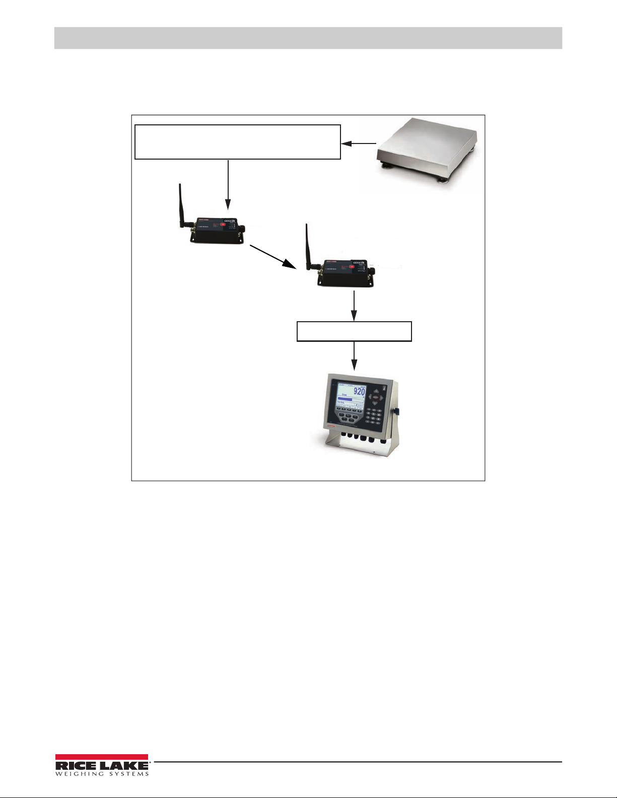
1.3 Overview
The SENDit offers an effective wireless load cell cable replacement in systems where it would be difficult to have a load cell
cable. Replacing the cable with an RF link, the output is then set to match the device that the cable was connected to.
Figure 1-1. SENDit Connectivity
One ChanSENDit Transmitter Transmitter
BenchMark Bench Scale
SENDit Reciever
920i Digital Weight Indicator

SENDit Wireless Load Cell Interface
4 Visit our website www.RiceLake.com
1.4 Front Panel
Figure 1-2. Transmitter Front Panel
Figure 1-3. Receiver Front Panel
Item No. Description
1 Load Cell connector (Transmitter) - located on the side of the unit.
mV/V Output (Receiver) - located on the side of the unit.
2 Transmitter Power LED – Indicates state of indicator power.
Steady short blinks – good battery (or AC power).
Two blinks then a pause – low battery.
Four blinks then a pause – very low battery.
Receiver Power LED – Indicates state of indicator power.
Steady short blinks – RF connected, good battery (or AC power).
Two short blinks then a pause – RF connected, low battery.
Four short blinks then a pause – RF connected, very low battery.
Steady long blinks – RF disconnected and good battery (or AC power).
Long blink, short blink then a pause – RF disconnected and low battery.
Long blink, three short blinks – RF disconnected and very low battery.
3 Power Button
Press & release – turns unit on
Press & hold for one to four seconds – will auto zero
Press & hold five seconds – turns unit off
4 Power In Connection – Located on the side of the unit. Type of power source will be checked on the overlay. All SENDit units
are currently 5-6 VDC.
5 Serial Port – located on the side of unit.
Table 1-2. Front Panel
2
1
3
4
5
2
1
3
4
5

Installation
© Rice Lake Weighing Systems ● All Rights Reserved 5
2.0 Installation
This section describes procedures for connecting load cell, power, and serial communications cables to the SENDit.
2.1 Unpacking and Assembly
SENDit transmitter and receiver units are factory paired. Take care when unpacking orders of multiple units to keep the paired
sets together. In the event a transmitter or receiver must be replaced or the units must be re-paired, see Figure 2-3 on page 6
for paring information.
Immediately after unpacking, visually inspect the contents to ensure all components are included (refer to the packing list) and
undamaged.
If any parts were damaged in shipment, notify Rice Lake Weighing Systems, and the shipper immediately.
2.2 Mounting the Enclosure
The SENDit can be mounted either vertically or horizontally to a flat surface.
If mounted inside an enclosure or I-beam, use the correct antenna for the environment and distance. Please call Rice Lake
Weighing Systems if assistance is needed to select an antenna, or reference the antenna selection guide in the appendix.
Antennas must be placed in appropriate line-of-sight for reliable communications.
Ensure antennas are securely connected to both the transmitter and receiver.
A standard antenna and coax connector are resistant to water, but not waterproof.
Seal the TNC base with an adhesive heat shrink boot if antenna is exposed to water.
Figure 2-1. Mounting Dimensions
Note
IMPORTANT
149 mm [5.866"]
135.5 mm [5.335"]
6.0 mm [0.236"]
9.70 mm [0.382"]
4.50 mm [0.177"]
66 mm [2.598"]
44.5 mm
[1.752"]
38.5 mm [1.516"]
Center Distance
39.8 mm [1.567"]
M4 or #8
FH Mounting
Screw X4
SENDit Wireless Load Cell Interface
6 Visit our website www.RiceLake.com
2.3 Cable Connections
2.3.1 Connect Transmitter
Using the optional pre-wired cable (Table 2-1) or the field wire-able connector (Figure 2-2), connect a SENDit transmitter to the
load cell or j-box; eliminating the need for a homerun cable.
See Section 4.0 on page 9 for calibration procedure.
SENDit Load Cell Wiring
Use cordset PN 162177
Figure 2-2. Field Wire-able Connection
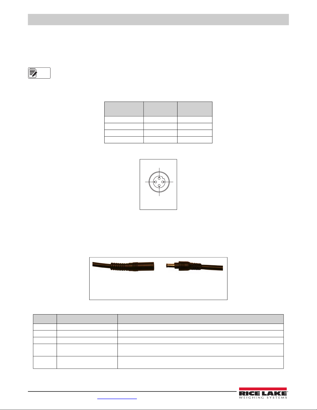
2.3.2 Connect Receiver
1. Connect the power source (Table 2-2) to the transmitter.
2. Using a 9 pin serial cable, connect the transmitter to a computer. This allows setup with the MSI TranSend mV/SENDit
Receiver Calibration program. See Section 4.0 on page 9.
Figure 2-3. Power Input Wiring
SENDit
Connector Pin # Wire Color Function
1 Brown +Excitation
2 White -Excitation
3 Blue +Signal
4 Black -Signal
Table 2-1. Load Cell TB-Input Device
Part No Description Comments
162172 6V Battery Charger Universal Power, US Plug. Requires changing plug type for international sales.
162173 6V Battery Option Kit Battery (161679) and interface cable (159817)
162175 Enclosure for 6V SLA Battery Used for installations where the battery needs to be rigidly mounted.
160109 6V Wall Cube, US Plug Power Adapter, 12W 6VDC Wall Mount. Universal Input 90-264VAC. 2.1mm Coax Power Plug.
US, Canada, Japan
160110 6V Wall Cube,
International Plugs
Power Adapter, 18W 6VDC Wall Mount. Universal Input 90-264VAC. 2.1mm Coax Power Plug.
Contains blades for international mains. US, UK, Europe, Aus, China
Table 2-2. Power Connection Options
Note
1
2
3
4
Male Connector
Power Input Cable 6VDC Battery Connector
or
120VAC Power
Adapter Connector
Indice
Altri manuali Rice Lake Apparecchiature di registrazione


Manuali Apparecchiature di registrazione popolari di altre marche


Strymon
Strymon NIGHTSKY Manuale utente

Mitsubishi Electric
Mitsubishi Electric 16CH DIGITAL RECORDER DX-TL5000U Manuale utente

Tews Technologies
Tews Technologies TPMC465 Manuale utente

Honeywell
Honeywell Excel 50 Manuale utente

SeaLevel
SeaLevel COMM+8.LPCI Manuale utente

Arturia
Arturia AUDIOFUSE STUDIO Manuale utente


