RIED Oculus Guida alla configurazione
Oculus / Aeron – General Guide
Oculus,
Oculus Ti,
Aeron.
Pan & Tilt Camera
General Guide
SSL DN122305 - v4.2
1 of 24

Oculus / Aeron – General Guide
Safety.
NSTALLAT ON SHOULD BE CARR ED OUT BY QUAL F ED PERSONNEL ONLY N ACCORDANCE W TH
THE APPL CABLE LOCAL CODES.
THE MANUFACTURER CAN ACCEPT NO L AB L TY FOR ANY DAMAGES OR LOSSES CAUSED DUE
TO NCORRECT OR MPROPER NSTALLAT ON
Read these instructions , Keep these instructions.
Follow all instructions and warnings.
nstall according to manufacturer’s instructions.
Do not open the camera unit, doing so invalidates the unit’s warranty.
Do not back-drive the pan or tilt axis of the camera. To do so will damage the motor drive mechanism and will
invalidate the warranty.
Do not use caustic or abrasive cleaning products on the unit.
n situations where there could be a risk of injury should any part of the assembly become detached for any
reason and fall, normal safety precautions should be employed.
A strong safety chain between the camera pan shaft base and the mounting surface is recommended.
Use only the power source types indicated in this user guide and ensure that the current rating of the supply
cable is adequate for the product.
All power supplies should be appropriately fused.
Take extra care lifting or moving camera units due to their weight.
Take care to allow space around the unit for Pan and Tilt motion.
Take care to avoid striking persons or objects when the camera is in motion.
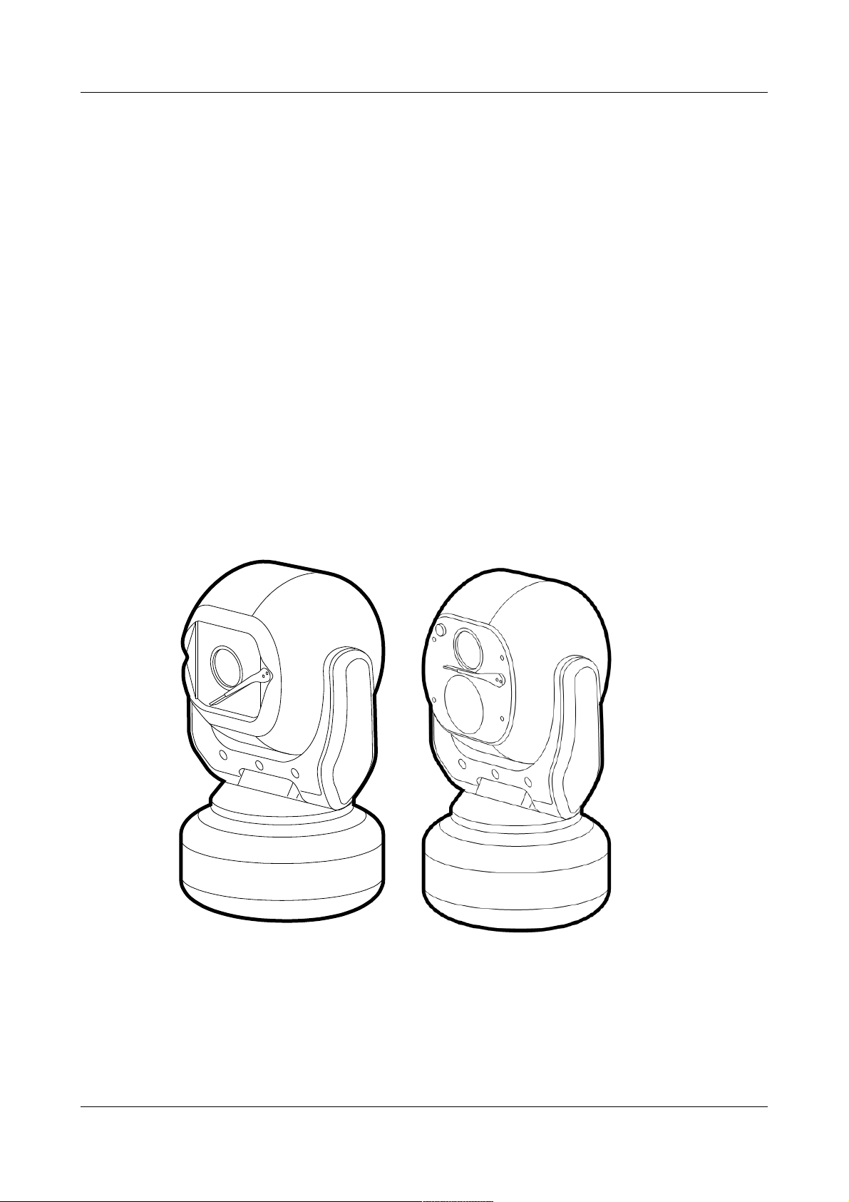
Introduction.
These are no ordinary cameras. Thanks to careful development and rigorous testing, these cameras are
equipped to survive in harsh environments and provide enhanced features. Two main models are available
to offer optical only or optical plus thermal imaging abilities.
The numerous benefits of both camera types include:
•Flat toughened glass window – scratch resistant, maintenance-free and optically correct,
•ntegral Wiper – to clean away rain and deposits caused by wind, sea spray and road traffic,
•Anodised aluminium castings, with powder coating to resist
corrosion in the harshness of marine environments,
•Stainless steel case fastenings,
•Optional washer system interface,
•Optional infra-red LED illumination system,
•Multiple native control protocols: RS-485 (Simplex/Half-duplex)
SSL DN122305 - v4.2
2 of 24
Oculus / Aeron – General Guide
Installation
Camera mounting
The camera is designed to be mounted upright or hanging. By
nature of its rugged construction the camera is a heavy item and
thus requires a substantial and stable mounting. The camera can
be supplied with an optional mount adaptor to allow fixing to
industry standard brackets, towers or columns.
The mount adaptor has two cable entry points:
•(1) A pass-through hole in the end plate to allow the composite
cable to enter unseen from a column, tube or bracket type
mounting, plus
•(2) A conduit thread (M25) in the side wall to permit composite
cable entry via a flexible conduit attached to the adaptor.
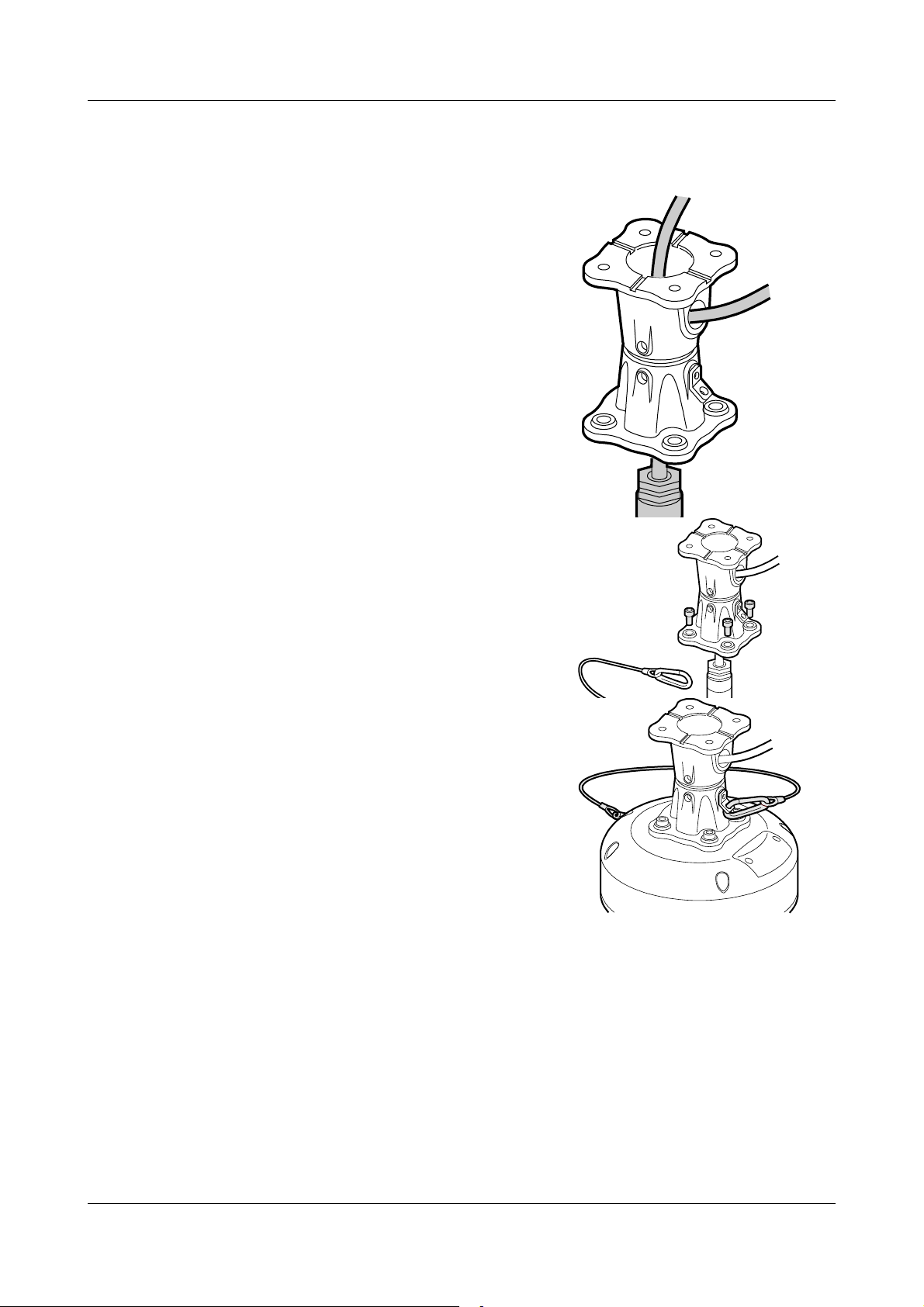
To mount the camera
1Thread the composite cable through the appropriate entry hole
into the mount adaptor before it is fixed to the column or
bracket.
2To avoid placing strain upon the electrical connections,
arrange the composite cable such that approximately 120mm
of the weatherproof connector protrudes out from the smaller
plate that will connect to the camera.
3 Secure the mount adaptor to the supporting structure using
M8 bolts, washers and Nyloc® type nuts where appropriate.
4 Remove the four hex head bolts from the camera base and
push the connector back into the mount adaptor.
5Offer the camera to the mount adaptor and clip the lanyard
onto the lug of the mount adaptor. n addition to being an
essential safety device during operation, the lanyard is useful
as a temporary hanging point when the camera is being
mounted in the inverted position.
6 Carefully note the orientation notches of cable connector and
camera socket. Align the notches accordingly and insert the
connector onto the socket of the camera base. Twist the
connector’s retaining ring until it fully locks into place.
7 Align the four holes of the mount adaptors with those on the
camera base and insert the four hex head bolts.
8 Tighten the bolts to approximately 1.6Kg/m. Do not over
tighten bolts.
IMPORTA T: Always use sprung washers and yloc® nuts
in order to significantly reduce the possibility of bolts working loose due to vibration during
operation.
Cable entry path must be watertight to avoid ingress and build-up of water around the connector.
SSL DN122305 - v4.2
3 of 24
1
2
Oculus / Aeron – General Guide
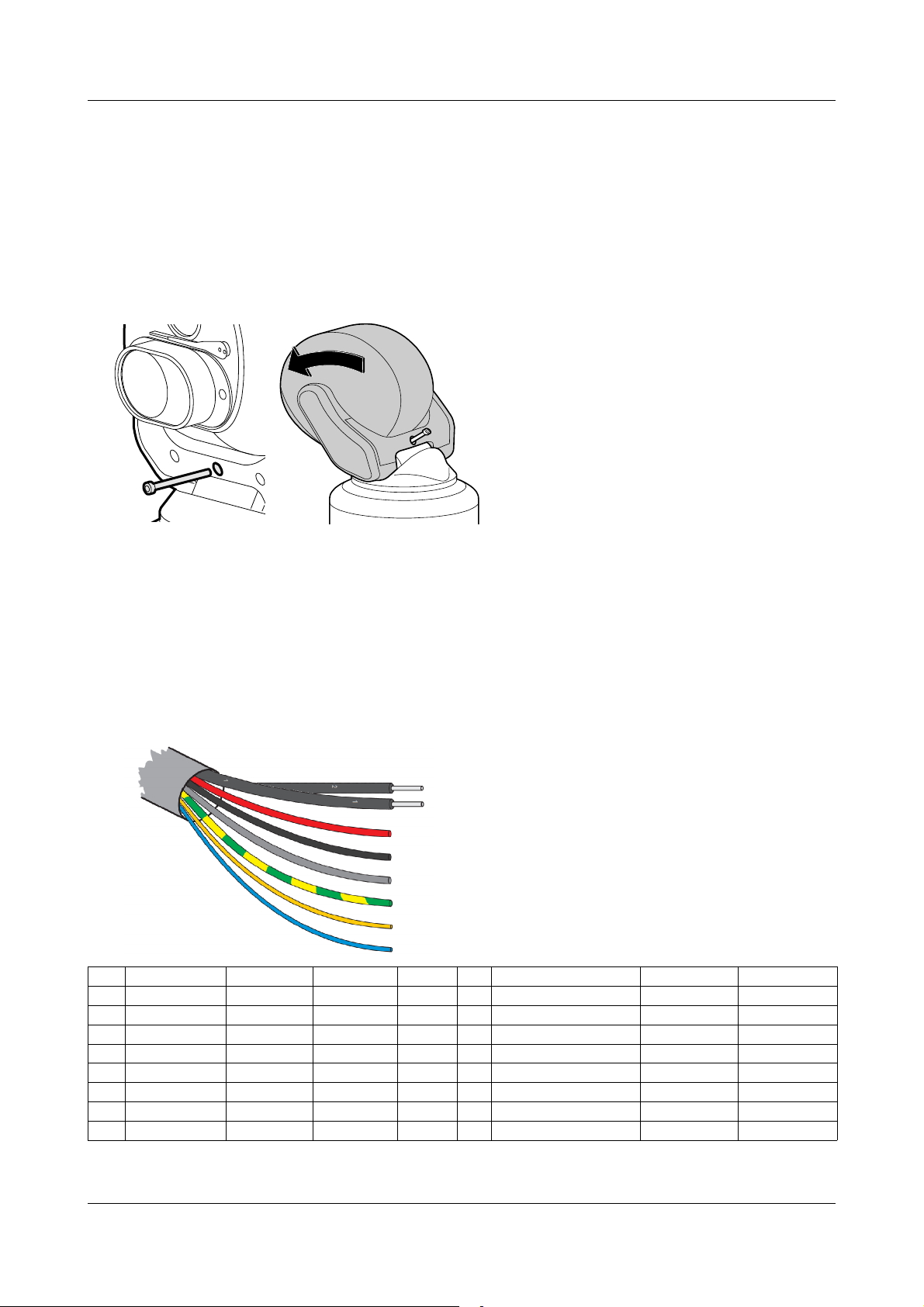
To tilt the camera head
When mounting upright, the camera head can be cantered to allow it a field of view clear of the pan motor
section of the housing.
1Unscrew and withdraw the M5 socket head retaining bolt from the middle of the front of the yoke.
2Carefully tip the yoke assembly forward.
3Re-insert the bolt from the rear of the yoke and tighten to approximately 0.97Kg/m. Do not over
tighten the bolt.
The camer's Setup > Configuration menu should be adjusted to indicate that the head has been cantered,
in order to ensure appropriate operation.
Camera power requirements.
nput voltages 28VDC (24-30 VDC) / 24VAC (RMS)
Power 70W (150W peak) Standard payloads.
100W (150W peak) Large / Dual payloads.
These figures do not include the requirements of any large payloads, optional heating or cooling devices
added within the camera enclosures, nor optional infra-red lighting systems.
CA-RCM Installation Cable.
Multiway Connector Contact Assignments,
Pin Function Conductor Pin Function Conductor
A Power + (Pos) Red M Earth (Chassis) Green/Yellow
B Power - (Neg) Black || Cable screen Grey (Drain wire) Common to pin M
F Video 1 Ground Coax 1 Screen N Aux / Washer Relay Pos Orange Closing Contact
G Video 1 Signal Cox 1 Core P Aux / Washer Relay Neg White Closing Contact
H Video 2 Ground Coax 2 Screen S Video 2 Signal Coax 2 Core
K RS485 (Data +) UTP Yellow
L RS485 (Data -) UTP Blue
SSL DN122305 - v4.2
4 of 24
Oculus / Aeron – General Guide
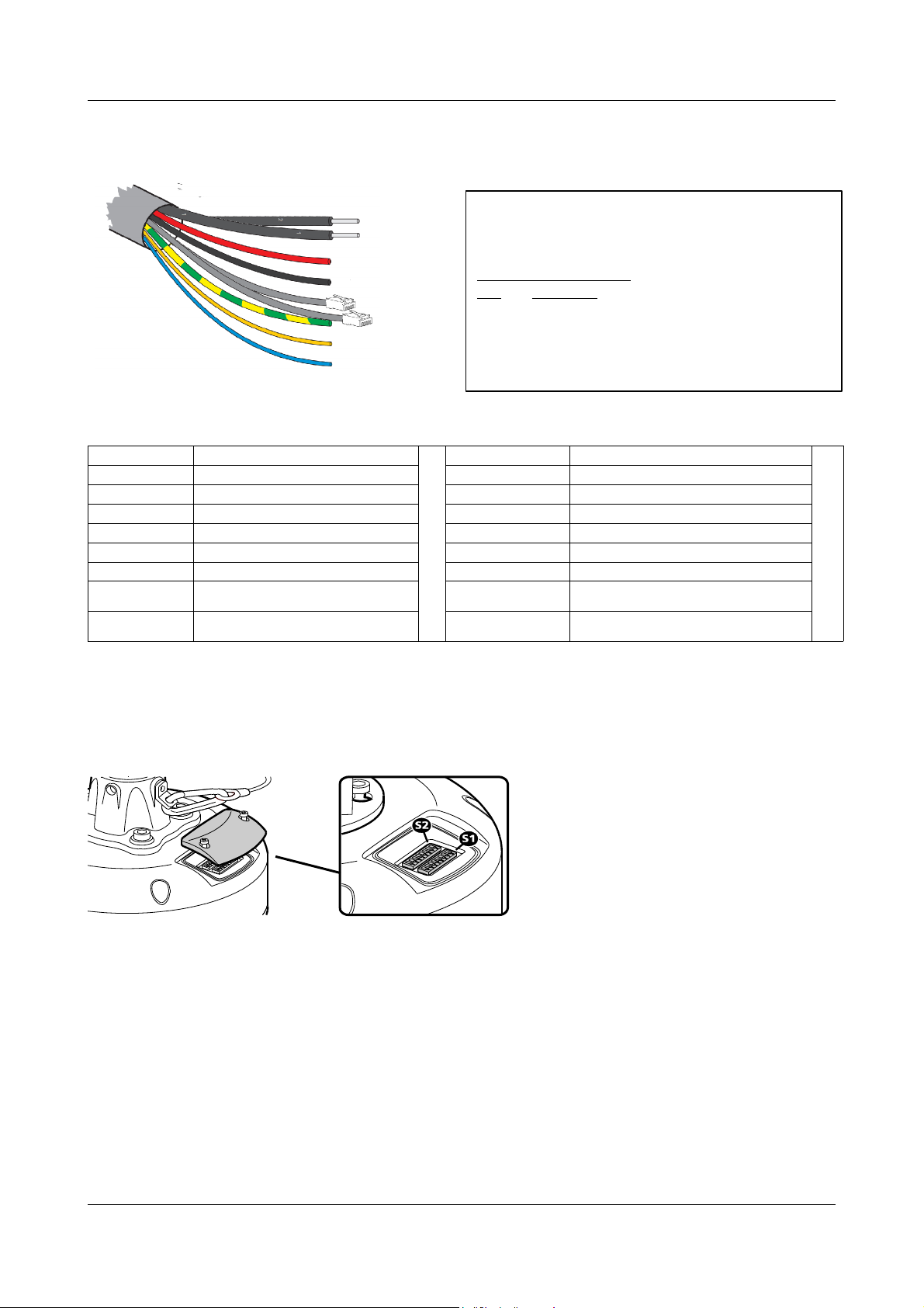
CA-UCM Installation Cable.
Multiway Cable Conductor Assignments.
Conductor Function Conductor Function
Red PTZ Power + (Pos) [26-32VDC] Green/Yellow Earth (Chassis)
Black PTZ Power - (Neg) Grey (Drain wire) Cable screen – overall multicore shield.
Orange Aux / Washer Relay Pos – (Specific models only)
Coaxial 1 Composite Video 1 - miniRG59 White Aux / Washer Relay Neg – (Specific models only)
Coaxial 2 Composite Video 2 - miniRG59 Brown Pass-through Power Pos
Blue Pass-through Power Neg
Yellow (UTP) UTP - RS485 (Data +) Cat5e - Grey Net 1 (A) – Ethernet network – PTZ/Side camera
payloads
Blue (UTP) UTP - RS485 (Data -) Cat5e - Blue Net 2 (B) – Ethernet network – Passthrough to top
payload
Configuration switches
These switches set the address and protocol of the camera. f all switches are off then the address is taken
from the camera’s internal memory and can be set using the menu. The default for the internal memory is 1.
Settings related to telemetry control can be configured using two banks of switches (S1 and S2) located
behind a removable panel within the hub of the camera. To access the switches, remove the two retaining
screws and remove the panel:
SSL DN122305 - v4.2
5 of 24
Netwok connection leads.
Cat5/8P8C pinout configuration – 10/100BASET
(TIA568B)
Network connectors.
Pin Function
1 Tx D+
2 Tx D -
3 Rx D+
6 Rx D -

Oculus / Aeron – General Guide
Device ID address (block S1, switches 1 to 8)
The 8 switches are the binary code of the address so switch 1-1 is equal to 1, switch 1-2 to 2, switch 1-3 to 4,
etc. (powers of 2).
For instance, an address of 65 would be 1+64, requiring switches 1 and 7 to be on.
Some sample values are in the table below.
Camera S1-1 S1-2 S1-3 S1-4 S1-5 S1-6 S1-7 S1-8
address (1) (2) (4) (8) (16) (32) (64) (128)
0 Off Off Off Off Off Off Off Off
1 On Off Off Off Off Off Off Off
2 Off On Off Off Off Off Off Off
3 On On Off Off Off Off Off Off
4 Off Off On Off Off Off Off Off
5 On Off On Off Off Off Off Off
-
100 Off Off On Off Off On On Off
101 On Off On Off Off On On Off
-
255 On On On On On On On On
f all switches are off then the address is taken from the internal memory and can be set using the
communications menu. The default setting for the internal memory is device No.1.
The boot screen will indicate which address is selected and whether it was set by the switches or by the
firmware. [S] - Selected on Switches or [F] - Selected in Firmware/Menu.
Protocol (block S2, switches 1 to 5)
Sets the protocol and communication parameters.
The protocols that can be selected using the protocol switches are:
Protocol S2-1 S2-2 S2-3 S2-4 S2-5 #
Set using camera menu Off Off Off Off Off 0
FV300, 9600, 8, Odd, 1 On Off On On Off 13
Pelco-D, 9600, 8, N, 1 Off On On Off On 22
Pelco-D, 2400, 8, N, 1 Off On Off On Off 10
Pelco-P, 9600, 8, N, 1 On Off Off Off Off 1
Pelco-P, 4800, 8, N, 1 Off On Off Off Off 2
Philips, 9600, 8, N, 1 On On Off Off Off 3
Philips, 2400, 8, N, 1 Off Off On Off Off 4
Vicon, 4800, 8, N, 1 On Off On Off On 21
Vicon, 9600, 8, N, 1 Off Off On Off On 20
OCP, 9600, 8, N, 1 On On On On On 31
Unsupported switch settings default the protocol to that which is set in the camera menu.
f all protocol switches are off then the protocol is taken from the internal memory and can be set using the
menu. The default setting for the internal memory is Pelco-D, 9600 baud, 8 data bits, no parity and 1 stop
bit.
The boot screen will indicate which protocol is selected and whether it was set by the switches or by the
firmware. [S] Selected on Switches or [F] Selected in Firmware/menu.
Termination (block S2, switch 8)
Sets the termination for the RS485 interface. For protocols which use RS485 control signals via the twisted
pair link within the camera’s composite cable, you can determine whether or not the camera is terminated.
The camera should be terminated whenever it is situated as either the only device connected to a controller
or the last device within a chain of similar devices.
Termination S2-8
Termination off Off
Termination on On
Note: Switches 6 and 7 on block S2 are unused and should remain off.
SSL DN122305 - v4.2
6 of 24

Oculus / Aeron – General Guide
Start-up POST information display.
Power On Self Test
Open Platform
Version n.nnn (xxxx) C1
SN:FFFFFFFF Cam:001 E0000
P:PelcoD, 600,8N1 M:002
bqhept
Pan:00000000 Til:00000000
Version : Firmware version number and check code.
C1 : Firmware security code - {Factory use only}
S : Main board serial number
Cam: Selected Camera/Device address number.
Exxxx : Extended functions selection - {Factory use only}
P: Pre-selected Protocol information;
(Protocol Name, Baud, Data/Parity/Stop bits)
M: Menu access Preset number, (EXT-POS).
Bqhept : Firmware status codes {Factory use only}
Pan: Til: Encoder power-on test count values – {For
servicing use}
Example values shown.
Oculus Camera Menus.
OSD Menu navigation.
To allow interaction with the On Screen Display menus from a variety of third-party control equipment the
menu navigation uses basic Pan/Tilt and Preset-Position recall controls that are widely supported.
These are Tilt (Up/Down), Pan (Right/Left), Recall/Goto Preset-1 and Recall/Goto Preset-2*.
The Zoom+ (Tele) and Zoom- (Wide) controls may also be used.
==============================================================
avigation Controls.
Recall Preset-2 To open the OSD Menu screen
Recall Preset-1 (or Zoom+) To SELECT a highlighted item (or toggle value).
Tilt (Up/Down) To move between items within the menus.
Pan (Right/Left) To ncrease/Decrease values within a list.
Zoom- (Wide) To exit a menu (or Select Exit from menu list)
Menu items that start with the greater-than ( > ) character provide access to sub-menus.
The base preset number (OSD Menu) can be set in the Configuration menu.
The default is 2, for use with controllers of limited preset numbering.
Alternative Recall Preset-199 for systems with 3-digit recall.
( * ) The use of Preset-2 to access the OSD Menus may be changed within the SETUP menus to allow a
different value to be used if desired, (Ref. SETUP > CONF GURAT ON menu, EXT-POS value).
==============================================================
Configuration of the camera takes place using the internal menu. There are two versions:
- A quick menu that contains only the most commonly used settings;
- A comprehensive main menu where all settings are accessible.
Default password: AAAAAA.
The two menus are accessed in slightly different ways.
SSL DN122305 - v4.2
7 of 24

Oculus / Aeron – General Guide
The Quick Installation menu.
To access the quick installation menu you need to issue a Go To Preset-198 command to the camera.
The menu contains only the most common settings that may need to be changed during installation or
service:
Note: he Quick menu does not require a password to gain access to key camera settings (and also
provides a backdoor entrance to the main Setup menu. herefore you are recommended to disable the quick
menu (Hide quick menu option) once all configuration settings have been made.
The menu contains only the most common settings that may need to be changed during installation or
service:
Open Platform
Version n.nnn (xxxx) xx
SN: FFFFFFFF POST: 000000000
>Communications
Orientation Upright
Disable OSD Off
Hide quick menu Off
Setup menu
Reboot camera
Exit menu
Default values shown.
•>Communications accesses the settings for the camera D, the protocol and the communications
parameters such as baud rate and parity. See the section ‘Communications’ within the Main menu
chapter for details about each option.
•Orientation – sets the installation orientation for the camera. Cameras may be mounted in a hanging,
upright or upright tilted position. Setting the correct orientation will allow the camera to set the horizon
level. This setting requires a re-boot of the camera to take effect.
•Disable OSD – disables display of optional OSD telemetry messages such as the camera text, the
compass data and the date and time. ndividual items can be controlled from the Telemetry menu
accessed through the full setup menu. This option does not hide messages that are shown in response to
user actions.
•Hide quick menu – disables the access to this menu from preset 198. f this menu is enabled then it is
possible for a user to access the full setup menu without recourse to the password. f this menu is hidden
it can be re-enabled from the Miscellaneous menu via the full setup menu.
•Setup menu – provides access to the full setup menu where all of the camera options can be controlled.
No password is required. See the section ‘Setup’ within the Main menu chapter for details about each
option.
•Reboot camera – reboots the camera. This is required by some configuration changes and is also useful
if you suspect there may be a camera error as the Power-On Self Test (POST) is run.
SSL DN122305 - v4.2
8 of 24

Oculus / Aeron – General Guide
Main Root Menu
Version n.nnn (xxxx) xx
SN: FFFFFFFF POST: 000000000
>Lens options
>Goto preset
>Run tour
Pan/Tilt Control Normal
>Setup (protected)
Using SSUTILITY Off
CAM2 control Timed
Minimum zoom Off
Reboot camera
Exit menu
Send a Preset-2* command (or Preset-199) to access the
Main Root Menu.
Preset-2 is the Factory default value which may be adjusted
via the CONF GURAT ON sub-menu,
change the value of EXT-POS (Ref. Pag.10).
Lens Options is only displayed if a lens with enhanced
functions is installed.
Lens Options
Goto Preset
Run Tour
Pan/Tilt Control
Setup (Protected)
Using SSUtility
CAM2 Controlled
Minimum Zoom
Reboot Camera
Provides access to enhanced lens functions sub-menu where this is supported .
- Shows a list of the presets. Selecting a preset will apply it. Presets that are defined
are marked with an ‘@’ symbol. Tjhose allocated to Preset Functions are marked with
an 'f' and cannot be recalled.
- Shows a list of the tours and mimic tours. Selecting a tour will run it.
- Sets the type of response to manual (Joystick) speed inputs for Pan and Tilt motion.
ormal sets a linear response, proportional to the input value.
For systems where Pelco D is the selected protocol:
Linear255 allows for a higher reolution of 255 speed values (non-standard).
Quad and Quad255 apply a quadratic response for finer slow-speed control.
- Accesses the setup and configuration menu (see below for details). The setup
password will be requested before access to the menu is allowed.
The default setting for the password is AAAAAA (6 characters).
– Allows specific functionality if the SSUtility computer programme is being used.
– Sets the control method for the secondary camera and lens if they are fitted.
Timed: uses Secondary mager Control to direct controls to the secondary camera. f
control is not toggled back to the Primary camera by the operator the function will time-
out automatically.
Sticky: will cause the change of control to the Secondary camera to remain until the
operator changes it – no time-out is applied.
FollowV: will cause the control to be applied to whichever camera image is being
displayed on the principle, video output No.1.
– Sets zoom limit for Front Mounted Magnifier lenses – Applies to specific models only.
– Resets the PT unit as though it has just been powered on. This is required by some
configuration changes and is also useful if you suspect there may be a camera error
as the POST is run.
The Setup (Protected) menus.
SSL DN122305 - v4.2
9 of 24

Oculus / Aeron – General Guide
Password Screen.
--------
????????
--------
A B C D E F G H I J K L M
N O P Q R S T U V W X Y Z
a b c d e f g h I j k l m
n o p q r s t u v w x y z
0 1 2 3 4 5 6 7 8 , . -
( ) / : ; < > ? “ ' + * =
SPC <-- --> DEL ESC OK NXT
The setup menu is protected by a password.
Move and select the highlighted character in the text
grid to add it to the password.
Next, highlight and select OK to submit the password
and open the SETUP menu.
Additional punctuation characters can be displayed by
selecting the NXT caption to change those shown in
that row.
The default setting for the password is AAAAAA
(6 characters).
The password can be changed within the
Miscellaneous section of the Setup menus.
Setup menu.
Version n.nnn (xxxx) xx
SN: FFFFFFFF POST: 000000000
>Camera 1 options
>Camera 2 options
>Communications
>Configuration
>Miscellaneous
>Presets
>Privacy zones
>Telemetry
>Tours
>Video settings
Exit menu
The SETUP menu contains sub-menus that allow the
settings of the camera operating parameters, preset
positions, tours, telemetry (on-screen display items)
and privacy zones.
Camera 1 Options
Camera 2 Options
Communications
Configuration
Miscellaneous
Presets
Privacy Zones
Telemetry
Tours
Video Settings
Exit Menu
- Provides access to the module specific options for the optical camera.
- Shown only if a thermal imaging or second video module is fitted.
- To access the sub-menu for serial telemetry settings
- To access the sub-menu for motion and control settings#
- To access the sub-menu for ancillary functions.
- To access the sub-menu for storing and recalling Preset Positions.
- To access the sub-menu for setting-up privacy zones – {where applicable}.
- To access the sub-menu for Ons Screen Display messages and captions.
- To access the sub-menu for configuration of Preset and Mimic Tours.
- To access the sub-menu for video output signals.
- To return to previous menu level.
Camera 1 options
SSL DN122305 - v4.2
10 of 24
Questo manuale è adatto per i seguenti modelli
2
Indice


