2136 7
THE BURNERS LEAVE THE FACTORY SET AT THESE VALUES
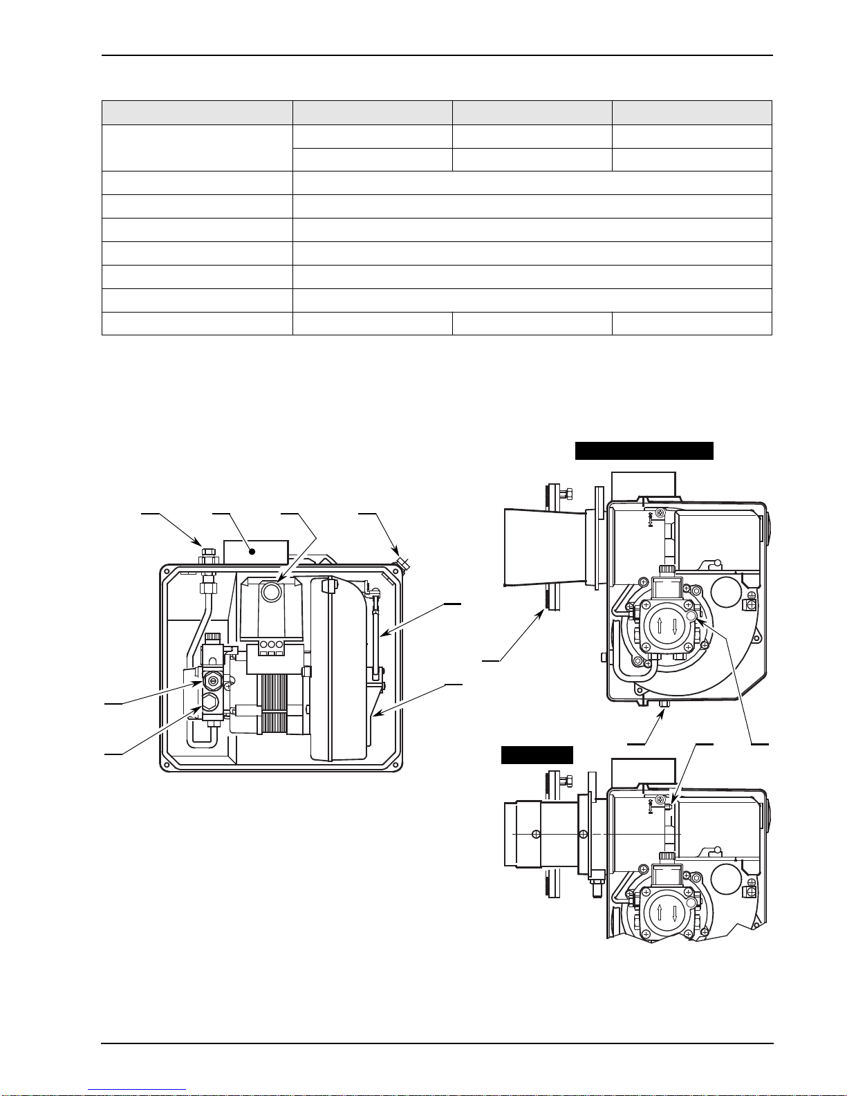
COMBUSTION HEAD SETTING (Only type 489T53)
This is done when fitting the nozzle, with the blast tube removed.
It depends on the output of the burner and is carried out by rotating the regulating rod, till the terminal
plane of the blast tube is level with the set-point, as indicated in the schedule.
In the sketch below, the combustion head is set for an output of 1.25 GPH at 8 bar
.
The shutter is level with set-point 3, as required by the schedule at page 6.
Combustion head settings indicated in the schedule are valid for most cases.
The setting of the fan output according to the installation should normally be done only through the air
damper. Should one subsequently want to retouch also the setting of the combustion head, with the
burner running, operate on the rod (1) with a 6 mm spanner (2) as follows:
TURNTOTHE RIGHT : (sign +)
In order to increase the volume of air entering the combustion chamber and thus diminishing its pres-
sure.
There is a reduction of CO2and the adhesion of the flame to the air diffuser disc improves. (Setting
advisable for ignitions at low temperatures).
TURNTOTHE LEFT : (sign –)
In order to reduce the volume of air entering the combustion chamber and thus increasing its pressure.
The CO2improves and the adhesion of the flame to the diffuser tends to reduce. (This setting is not
advisable for ignitions at low temperatures).
In any case do not bring the combustion head setting more than one point away from that indicated in
the schedule. One set-point corresponds to 3 turns of the rod;a hole (3) at its end facilitates counting
the number of turns.
TYPE Nozzle Pump
Pressure Comb. head
adjustment Air damper
adjustment
bar Set-point Set-point
490T53 Danfoss 0.60 GPH - 80°H 8 – 3.8
492T57 Danfoss 0.75 GPH - 80°H 8 – 4.0
489T53 Danfoss 1.00 GPH - 80°H 8 2.5 3.9
3
Blast tube
Regulating rod
Shutter
Terminal plane of the blast tube
1
2 3
6
D5232 D5233
2
135