Ringdale Ethernet-Token Ring Manuale utente

Ethernet - Token Ring
Network Router
User Manual
RD2004112901 | Eth_Tring_Rout_Man.doc - 1 -

Version 1.6 November 2004
COPYRIGHT
Copyright 2002 © Ringdale UK Ltd. All rights reserved. No part of this
publication may be reproduced, transmitted, transcribed, stored in a
retrieval system, or translated into any language or any computer
language, in any form or by any third party, without prior
permission of Ringdale UK Limited.
DISCLAIMER
Ringdale UK Ltd. reserves the right to revise this publication and to make
changes from time to time to the contents hereof without obligation to notify
any person or organization of such revision or changes. Ringdale UK Ltd.
has endeavored to ensure that the information in this publication is
correct, but will not accept liability for any error or omission.
TRADEMARKS
All trademarks are hereby acknowledged.
Part No. 62-23280000
RD2004112901 | Eth_Tring_Rout_Man.doc - 2 -

Table of Contents
Introduction...................................................................................4
Installation ..................................................................................5
Using PeripheralVision® to Configure the Router...................7
IP Router Page.............................................................................8
Passwords....................................................................................9
Routing Table Page......................................................................9
Broadcast Forward Page............................................................ 11
PeripheralVision® Licensing.......................................................12
Token Ring Speed Settings..................................................... 13
Safety and Location Advice..................................................... 14
Technical Specification............................................................ 15
Troubleshooting Guide............................................................ 16
RD2004112901 | Eth_Tring_Rout_Man.doc - 3 -

Introduction
Ringdale’s 19-inch Ethernet -Token Ring Network Router provides
a solution for connecting an entire Ethernet network and an entire
Token Ring network. Printers, PCs and network peripherals
attached to both networks can interact with each other.
Ethernet connection is made with an RJ-45 connector, configured
to allow a straight cable to run to the 10baseT Ethernet Network.
Token Ring connection is made using a type 1 cable on a 9-way
DB connector or type 3 cable on an RJ-45 connector. The router
has the ability to automatically sense which Token Ring connection
is used as well as the Token Ring speed, at either 4MHz or 16MHz.
The router is designed to easily mount into an industry standard 19-
inch rack system for convenience. The router is configured and
managed remotely using Ringdale’s PeripheralVision® network
management software that can be installed on any Windows™
95/98/ME/NT/XT/2000/2003 PC on the Token Ring network.
Follow the steps detailed in this manual for quick installation of the
Ethernet -Token Ring Network Router.
Back to TOC.
RD2004112901 | Eth_Tring_Rout_Man.doc - 4 -

Installation
Front Panel Connections and LEDs
Connecting the Router to the Ethernet Network
Insert the RJ-45 10baseT cable from the Ethernet network into the
RJ-45 port marked Ethernet Network 1.
The Green RX LED will blink when the router receives data from
the Ethernet network.
The Red TX LED will blink when the router transmits data to the
Ethernet network.
The Yellow Link LED indicates that the Ethernet network
connection is functioning.
Connecting the Router to the Token Ring Network
Insert either a Type 3 cable with an RJ-45 connector or a Type 1
cable with a 9 way DB connector from the Token Ring network into
the RJ-45 or DB 9 port respectively marked Token Ring Network
2. The router will auto-sense which Token Ring connector is being
used.
RD2004112901 | Eth_Tring_Rout_Man.doc - 5 -

The Red Error LED will light when there is an error on the Token
Ring network.
The Green RX LED will blink when the router receives data from
the Token Ring network.
The Red TX LED will blink when the router transmits data to the
Token Ring network.
Powering the Router
Connect the power cable to the Power Supply socket on the Rear
panel of the router. Connect the other end of the power cable to the
mains electricity supply.
Switch the router on using the Power switch on the rear panel.
Important Note
If there is a delay in connecting the router to the Token Ring
network after power-up, it may be necessary to restart the router in
order to make a good link to the Token Ring network.
When using PeripheralVision, you should see two (2) routers, each
representing a different side of the router (token ring and ethernet).
If you do not see two, use the Ping button to locate the second
router (default 11.22.33.44 and 11.22.33.45).
Back to TOC.
RD2004112901 | Eth_Tring_Rout_Man.doc - 6 -

Using PeripheralVision® to Configure the Router
Full operational procedures for PeripheralVision® are detailed in
the program helpfile, refer to this if any problems are encountered
in the procedure detailed below.
1. Install PeripheralVision® onto a PC on the Ethernet Network One.
2. Ensure the router is installed on both networks.
3. Using the Locate NPMP® discovery tool in
PeripheralVision®, enter the default set IP
address (11.22.33.44). The router will appear
on the network map, it will be an icon similar to
the example on the left.
4. Left click twice on the icon to open the property pages of the
device. The default displayed page will be the Name page. This is
shown below:
5. In the Icon Title field, enter a name for the router that will allow it to
be identified on the PeripheralVision® network map.
Back to TOC.
RD2004112901 | Eth_Tring_Rout_Man.doc - 7 -

6. Using the arrows in the top right corner, scroll the pages and click
the first IP Router page, as shown here:
The following information needs to be entered onto this page (this
will be supplied by your network administrator).
IP Address Enter here the router’s IP address for the Ethernet
Network 1 (this will be the gateway for all Token Ring devices).
TCP/IP Subnet Mask Enter here the subnet mask for the Ethernet
Network 1.
Default Gateway IP Address Enter here the IP address of another
router. This will allow packets for unrecognized IP addresses to be
redirected to that router.
DNS Name Server Address Enter here the IP Address of the DNS
server if required (optional).
Local IP Address Enter here the router’s IP address for the Token
ring Network 2 (this will be the gateway for the Ethernet network).
Local IP Subnet Mask Enter here the subnet mask for the Token
ring Network 2.
Click Apply to register the new information. Both networks should
now communicate with the router.
Back to TOC.
RD2004112901 | Eth_Tring_Rout_Man.doc - 8 -

Passwords
It is strongly recommended that Passwords are set for access
to all router property pages in PeripheralVision® because of
the sensitive nature of the information that may be configured.
If required, access to set/change the information on the router
property page may be restricted using the Change Password
button. Click it to bring up the following window:
Enter New Password. Confirm Password and click OK.
Access to change the configuration will now be restricted to those
who have the Password.
Back to TOC.
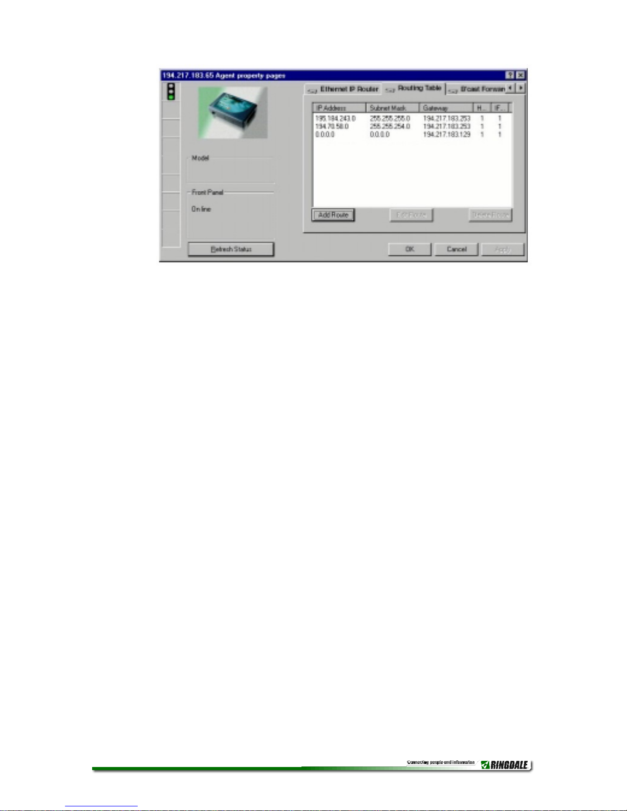
Routing Table Page
7. It is now necessary to tell the router where to route the IP packets.
This is done by creating a Routing Table. Use the arrows to scroll
the pages and select the Routing Table page. Make sure that the
whole IP range is passed over to the other network. Any packets
that are not in this range will be passed onto the Default Gateway
Address. An example of this setup is shown in the following
diagram.
To configure each route, click the Add Route button and enter the
information as described:
RD2004112901 | Eth_Tring_Rout_Man.doc - 9 -
IP Address Enter here the IP address of the subnet/range you
want to route to (enter a zero in the last segment of the IP address
for each range).
Subnet Mask Enter here the Subnet Mask of the above IP
Address, either for the Token Ring network or the Ethernet network.
Gateway Enter here the IP address of the router indicating the side
of the network the above IP addresses are on (for example, if the IP
addresses are on the Ethernet network, enter the address assigned
to the Local IP Address field previously - for the Token Ring
network use the address assigned to the first IP Address field).
H (Hops) Enter here the number of hops across networks or
subnets that are necessary to route the packets to the required IP
Address.
IF (Interface) Enter here the port through which the IP packets will
be routed (either the Ethernet Network 1 Port or the Token Ring
Network 2 Port).
Select a route from the list and click the Edit Route button to change the
configuration of an existing route.
RD2004112901 | Eth_Tring_Rout_Man.doc - 10 -
Indice
Altri manuali Ringdale Router di rete


Manuali Router di rete popolari di altre marche


NETGEAR
NETGEAR FS526T - Switch Manuale utente

Korenix
Korenix JetNet 5710G Series Manuale utente

Automated Logic
Automated Logic ZN551 Manuale del proprietario

Cisco
Cisco ASR 1000 Series Manuale dell'operatore

EnGenius
EnGenius ESR-9710 Manuale utente

Cisco
Cisco 805 Series Istruzioni operative e di sicurezza